


Voice Control Bot
Voice Control Bot is an autonomous engineering project developed by the NIST Robotics Club (NRC) at NIST University, Berhampur. A robot that responds to voice commands, utilizing speech recognition technology for hands-free operation.

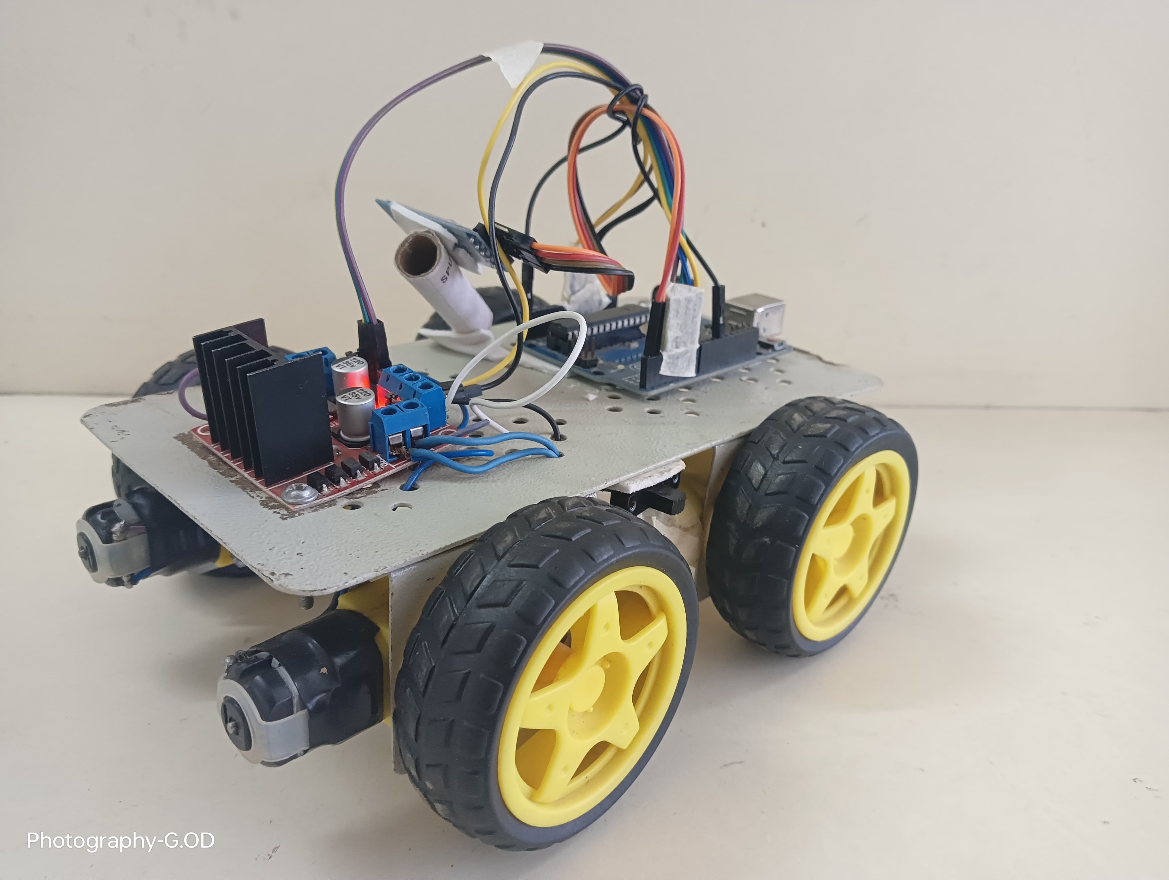
Project Overview
A robot that responds to voice commands, utilizing speech recognition technology for hands-free operation.
Technical Analysis
Powered by NRC AIAs a robotics and electronics expert, I'm excited to delve into the "Voice Control Bot" project. This is an excellent project for engineering students, combining concepts from embedded systems, robotics, and artificial intelligence (specifically speech recognition).
articleProject: Voice Control Bot
Project Description: A robot that responds to voice commands, utilizing speech recognition technology for hands-free operation.
label_important1. Technical Overview
The Voice Control Bot operates on a fundamental principle: converting spoken language into actionable commands for a mobile robot. Here's a detailed breakdown of the technical process:
- Voice Input & Acquisition: A microphone captures analog sound waves generated by the human voice. This analog signal is then converted into a digital audio stream.
- Speech Recognition (SR):
- Analog-to-Digital Conversion (ADC): The raw analog audio signal is converted into digital data (e.g., PCM - Pulse Code Modulation).
- Feature Extraction: Digital audio data is processed to extract relevant features that represent speech, such as Mel-Frequency Cepstral Coefficients (MFCCs). This step removes noise and irrelevant information.
- Acoustic Modeling: The extracted features are fed into an Acoustic Model (often a Deep Neural Network - DNN or Hidden Markov Model - HMM). This model predicts the most likely phonemes (basic units of sound) or sub-word units.
- Language Modeling: The predicted phonemes are then passed to a Language Model, which predicts the most probable sequence of words based on grammar and context. This combines with the Acoustic Model to form the Automatic Speech Recognition (ASR) system, outputting transcribed text.
- Cloud-based vs. On-device SR:
- Cloud-based (e.g., Google Speech-to-Text, Amazon Transcribe): Audio is streamed over Wi-Fi to a powerful server that performs the heavy-lifting of ASR. This offers high accuracy, large vocabulary, and multiple language support but requires internet connectivity and introduces latency. This is often the preferred choice for general-purpose speech recognition.
- On-device (e.g., TinyML, Edge Impulse, dedicated SR modules like EasyVR): ASR runs directly on the microcontroller or an embedded processor. This is suitable for specific keywords or small vocabularies, offers offline capability, and low latency but has limited accuracy and vocabulary due to computational constraints. For this project, given "hands-free operation" suggesting general commands, a cloud-based approach is often more practical unless targeting specific trigger words.
- Command Parsing & Interpretation: The recognized text string (e.g., "move forward", "turn left") is received by the microcontroller. A simple Natural Language Understanding (NLU) component (often rule-based using statements or string matching) parses this text to identify keywords and extract the intended command and any associated parameters.
if-else if - Action Execution: Based on the interpreted command, the microcontroller sends appropriate signals to actuators. For a mobile robot, this typically involves controlling DC motors via a motor driver.
- Motor Driver (H-bridge): An H-bridge circuit (like the L298N) allows the microcontroller to control the direction and speed of DC motors by switching the polarity of the voltage applied to the motor windings. Pulse Width Modulation (PWM) signals from the microcontroller can control the motor speed.
- Feedback (Optional): LEDs, a small display, or even simple beeps can provide visual or auditory feedback to the user about the robot's status or recognized command.
Architecture Flow:
[Microphone] -> [Analog-to-Digital Converter (ADC)] -> [Digital Audio Stream] | v (via Wi-Fi/Internet for Cloud SR) [Cloud Speech Recognition API] -> [Text Command] | v (via Wi-Fi/Internet for Cloud SR, or Serial/GPIO for On-device SR) [Microcontroller (ESP32)] | v [Command Parsing Logic] -> [Motor Control Logic] | v [Motor Driver (e.g., L298N)] -> [DC Geared Motors] -> [Robot Movement]
label_important2. Components Required
Here's a comprehensive list of components, focusing on using an ESP32 due to its integrated Wi-Fi (essential for cloud-based SR) and good processing power.
- Microcontroller Board:
- ESP32 Development Board: (e.g., ESP32-WROOM-32 DevKitC, NodeMCU-ESP32).
- Why: Built-in Wi-Fi and Bluetooth, dual-core processor, sufficient GPIOs, ADCs, and DACs. Essential for connecting to cloud SR services.
- ESP32 Development Board: (e.g., ESP32-WROOM-32 DevKitC, NodeMCU-ESP32).
- Motor Driver:
- L298N Motor Driver Module:
- Why: Inexpensive, capable of driving two DC motors, widely available. Handles higher current than the microcontroller's GPIOs.
- Alternatives: DRV8833 (smaller, more efficient for low voltage), BTS7960 (for higher current/power motors).
- L298N Motor Driver Module:
- Motors:
- 2x DC Geared Motors (with wheels): (e.g., Yellow TT Gear Motors, 3-6V)
- Why: Provide sufficient torque for robot movement. Geared motors offer lower RPM but higher torque.
- 2x DC Geared Motors (with wheels): (e.g., Yellow TT Gear Motors, 3-6V)
- Microphone Module:
- INMP441 I2S Digital Microphone Module:
- Why: High-precision digital output, noise cancellation, less prone to analog noise. Connects directly to I2S interface on ESP32. Ideal for audio input for SR.
- Alternative (simpler, analog): MAX9814 Electret Microphone Amplifier Module (requires ESP32 ADC). Less ideal for high-fidelity audio for SR.
- INMP441 I2S Digital Microphone Module:
- Power Supply:
- Battery Pack: (e.g., 4x AA battery holder for 6V, or 18650 Li-ion battery pack with holder for 3.7V/7.4V)
- Why: Powers the entire robot, including motors and microcontroller.
- DC-DC Buck Converter (optional but recommended for stable power): (e.g., LM2596 module)
- Why: If using a higher voltage battery (e.g., 7.4V for motors), a buck converter can step down voltage to 5V for the ESP32 (via its VIN pin or 5V pin) and the motor driver logic.
- Battery Pack: (e.g., 4x AA battery holder for 6V, or 18650 Li-ion battery pack with holder for 3.7V/7.4V)
- Chassis & Wheels:
- Robot Chassis Kit: (e.g., 2-wheel drive smart car chassis kit with caster wheel).
- Why: Provides a frame for mounting components and allows for mobility.
- Robot Chassis Kit: (e.g., 2-wheel drive smart car chassis kit with caster wheel).
- Cables & Connectors:
- Jumper Wires (Male-to-Male, Male-to-Female): For making connections.
- USB Micro-B Cable: To program the ESP32.
- Prototyping:
- Breadboard (Optional): For initial circuit testing before final assembly.
- Miscellaneous:
- Small Caster Wheel: For 2-wheel drive robots, provides stability.
- Screws, Nuts, Standoffs: For mounting components.
- Soldering Iron & Solder: For permanent connections (if not using breadboard).
- Velcro/Double-sided Tape: For securing components.
label_important3. Circuit Diagram Description
This description assumes using an ESP32, L298N motor driver, and INMP441 I2S microphone.
Power Distribution:
- The battery pack (e.g., 6V) connects to the L298N motor driver's VCC/12V pin (the high-voltage input for motors) and GND.
- The L298N also has a 5V output (via its internal regulator, but only if its VCC/12V input is 7V-12V). If your battery is 6V, or for better stability, connect a separate DC-DC Buck Converter to the battery.
- Connect the output of the DC-DC Buck Converter (set to 5V) to the ESP32's 5V pin (or VIN if available and regulated) and the L298N's 5V Enable/Logic power pin.
- Ensure all GNDs are common (ESP32 GND, L298N GND, Battery GND, Mic GND).
ESP32 to L298N Motor Driver Connections: The L298N controls two motors (Motor A and Motor B). Each motor requires two input pins for direction and one enable pin for speed control (using PWM).
- L298N Input Pins (Logic Control): Connect these to ESP32 GPIO pins. Choose any available digital GPIOs.
- (L298N Motor A, Direction 1) $\rightarrow$ ESP32
IN1GPIO 16 - (L298N Motor A, Direction 2) $\rightarrow$ ESP32
IN2GPIO 17 - (L298N Motor B, Direction 1) $\rightarrow$ ESP32
IN3GPIO 18 - (L298N Motor B, Direction 2) $\rightarrow$ ESP32
IN4GPIO 19
- L298N Enable Pins (Speed Control):
- (L298N Motor A Enable) $\rightarrow$ ESP32
ENA(Must be a PWM-capable pin)GPIO 26 - (L298N Motor B Enable) $\rightarrow$ ESP32
ENB(Must be a PWM-capable pin)GPIO 27 - Note: Some L298N modules have and
ENAjumpered to VCC, disabling PWM. Remove the jumpers if you want speed control.ENB
- L298N Power Pins:
- (or
VCCterminal) $\rightarrow$ Battery Pack Positive (e.g., 6V)+12V - (L298N) $\rightarrow$ Battery Pack Negative, and ESP32 GND.
GND - (L298N Logic Power / ENA/ENB jumpered input) $\rightarrow$ 5V output from Buck Converter or ESP32 5V.
5V
L298N to DC Motors Connections:
- (L298N) $\rightarrow$ Motor A terminal 1
OUT1 - (L298N) $\rightarrow$ Motor A terminal 2
OUT2 - (L298N) $\rightarrow$ Motor B terminal 1
OUT3 - (L298N) $\rightarrow$ Motor B terminal 2
OUT4- Note: If motors spin in the wrong direction, simply swap the connections for that motor.
ESP32 to INMP441 I2S Microphone Connections: The INMP441 is an I2S (Inter-IC Sound) digital microphone. It has specific pins for I2S communication.
- (INMP441) $\rightarrow$ ESP32
VCC3.3V - (INMP441) $\rightarrow$ ESP32
GNDGND - (Serial Clock) $\rightarrow$ ESP32
SCK(I2S SCK pin)GPIO 25 - (Word Select / Left-Right Clock) $\rightarrow$ ESP32
WS(I2S WS pin)GPIO 33 - (Serial Data) $\rightarrow$ ESP32
SD(I2S SD pin)GPIO 32 - (Left/Right Channel Select) $\rightarrow$
L/Rfor Left Channel (orGNDfor Right Channel). This is typically tied to GND for most single-channel usage.3.3V
Summary of Pin Connections:
| Component | Pin | Connects To | Description |
|---|---|---|---|
| ESP32 | GPIO 16 | L298N IN1 | Motor A Direction 1 |
| GPIO 17 | L298N IN2 | Motor A Direction 2 | |
| GPIO 18 | L298N IN3 | Motor B Direction 1 | |
| GPIO 19 | L298N IN4 | Motor B Direction 2 | |
| GPIO 26 | L298N ENA | Motor A Speed Control (PWM) | |
| GPIO 27 | L298N ENB | Motor B Speed Control (PWM) | |
| GPIO 25 | INMP441 SCK | I2S Serial Clock for Microphone | |
| GPIO 33 | INMP441 WS | I2S Word Select for Microphone | |
| GPIO 32 | INMP441 SD | I2S Serial Data for Microphone | |
| 3.3V | INMP441 VCC | Power for Microphone | |
| 5V (or VIN) | L298N 5V, Buck | Power for L298N logic, Buck converter input | |
| GND | All GNDs | Common Ground | |
| L298N | VCC (12V) | Battery + | Motor Power Input |
| GND | Battery -, ESP32 GND | Common Ground | |
| 5V (Logic) | ESP32 5V/Buck Output | Logic power for L298N, if not self-regulated | |
| OUT1, OUT2 | Motor A | Motor A Connections | |
| OUT3, OUT4 | Motor B | Motor B Connections | |
| INMP441 | VCC | ESP32 3.3V | Power for Microphone |
| GND | ESP32 GND | Ground for Microphone | |
| SCK, WS, SD | ESP32 I2S pins | I2S Digital Audio Interface | |
| L/R | GND (typically) | Left/Right Channel Select (tied to GND for left) | |
| DC Motors | 2 terminals | L298N OUTs | Motor A and Motor B connections |
| Battery | Positive | L298N VCC | Main Power Source |
| Negative | All GNDs | Common Ground | |
| Buck Conv. | Input | Battery +,- | Takes Battery Voltage |
| Output (5V) | ESP32 5V, L298N 5V | Regulated 5V for Logic |
Important Considerations:
- Always connect wires first.
GND - Double-check polarity for batteries and components.
- Ensure the L298N's 5V regulator is supplying enough current for its logic if you rely on it, or use a dedicated 5V supply (like from a buck converter). If your battery voltage is below 7V, the L298N's internal 5V regulator won't work, and you must supply 5V to its logic directly.
label_important4. Source Code
For this project, directly integrating real-time audio streaming from ESP32 to a cloud SR API and handling the complex HTTP/WebSocket protocols can be quite extensive for a single Arduino sketch, especially when also handling motor control.
Therefore, I will provide a robust robot control code driven by a String command. This
StringProgramming Language: C++ (Arduino IDE for ESP32)
C++#include <Arduino.h> // Standard Arduino library // --- Motor Driver Pin Definitions (L298N) --- // Motor A (Right Motor) #define ENA_PIN 26 // Enable/PWM pin for Motor A (Right) #define IN1_PIN 16 // Direction pin 1 for Motor A #define IN2_PIN 17 // Direction pin 2 for Motor A // Motor B (Left Motor) #define ENB_PIN 27 // Enable/PWM pin for Motor B (Left) #define IN3_PIN 18 // Direction pin 1 for Motor B #define IN4_PIN 19 // Direction pin 2 for Motor B // Motor Control Parameters const int MOTOR_SPEED_HIGH = 255; // Max speed (0-255 for PWM) const int MOTOR_SPEED_LOW = 100; // Low speed for turning // --- Speech Recognition (Conceptual / Simulated) --- // In a real application, this would involve: // 1. WiFi/Network setup (for cloud SR) // 2. I2S Audio capture from INMP441 // 3. Streaming audio to a cloud SR API (e.g., Google Speech-to-Text) // 4. Parsing the JSON response from the SR API to get the text command. // // For simplicity and demonstration, we'll simulate receiving a command // via Serial Monitor input or a predefined list. // --- Function Prototypes --- void setupMotors(); void moveForward(int speed); void moveBackward(int speed); void turnLeft(int speed); void turnRight(int speed); void stopBot(); void processCommand(String command); void setup() { Serial.begin(115200); // Initialize Serial communication for debugging and input Serial.println("Voice Control Bot - Initializing..."); setupMotors(); // Configure motor pins stopBot(); // Ensure motors are off at startup Serial.println("Robot Ready. Enter commands: 'forward', 'backward', 'left', 'right', 'stop'"); Serial.println("--------------------------------------------------------------------------"); } void loop() { // Simulate receiving a command. In a real scenario, this 'command' // would come from your speech recognition module/service. if (Serial.available()) { String command = Serial.readStringUntil('\n'); // Read until newline command.trim(); // Remove leading/trailing whitespace command.toLowerCase(); // Convert to lowercase for easier matching Serial.print("Received command: "); Serial.println(command); processCommand(command); } // Add a small delay to prevent rapid command processing if no input delay(10); } // --- Motor Control Functions --- // Initializes all motor control pins void setupMotors() { pinMode(ENA_PIN, OUTPUT); pinMode(IN1_PIN, OUTPUT); pinMode(IN2_PIN, OUTPUT); pinMode(ENB_PIN, OUTPUT); pinMode(IN3_PIN, OUTPUT); pinMode(IN4_PIN, OUTPUT); // Set initial motor states to LOW (stopped) digitalWrite(IN1_PIN, LOW); digitalWrite(IN2_PIN, LOW); digitalWrite(IN3_PIN, LOW); digitalWrite(IN4_PIN, LOW); // Set initial PWM values to 0 (stopped) analogWrite(ENA_PIN, 0); analogWrite(ENB_PIN, 0); } // Moves the robot forward void moveForward(int speed) { Serial.println("Moving Forward..."); digitalWrite(IN1_PIN, HIGH); // Motor A forward digitalWrite(IN2_PIN, LOW); digitalWrite(IN3_PIN, HIGH); // Motor B forward digitalWrite(IN4_PIN, LOW); analogWrite(ENA_PIN, speed); // Set speed for Motor A analogWrite(ENB_PIN, speed); // Set speed for Motor B } // Moves the robot backward void moveBackward(int speed) { Serial.println("Moving Backward..."); digitalWrite(IN1_PIN, LOW); // Motor A backward digitalWrite(IN2_PIN, HIGH); digitalWrite(IN3_PIN, LOW); // Motor B backward digitalWrite(IN4_PIN, HIGH); analogWrite(ENA_PIN, speed); // Set speed for Motor A analogWrite(ENB_PIN, speed); // Set speed for Motor B } // Turns the robot left by moving right motor forward and left motor backward void turnLeft(int speed) { Serial.println("Turning Left..."); digitalWrite(IN1_PIN, HIGH); // Right motor forward digitalWrite(IN2_PIN, LOW); digitalWrite(IN3_PIN, LOW); // Left motor backward (or very slow forward) digitalWrite(IN4_PIN, HIGH); analogWrite(ENA_PIN, speed); // Right motor speed analogWrite(ENB_PIN, MOTOR_SPEED_LOW); // Left motor slower (or reverse) } // Turns the robot right by moving left motor forward and right motor backward void turnRight(int speed) { Serial.println("Turning Right..."); digitalWrite(IN1_PIN, LOW); // Right motor backward (or very slow forward) digitalWrite(IN2_PIN, HIGH); digitalWrite(IN3_PIN, HIGH); // Left motor forward digitalWrite(IN4_PIN, LOW); analogWrite(ENA_PIN, MOTOR_SPEED_LOW); // Right motor slower (or reverse) analogWrite(ENB_PIN, speed); // Left motor speed } // Stops the robot void stopBot() { Serial.println("Stopping..."); digitalWrite(IN1_PIN, LOW); digitalWrite(IN2_PIN, LOW); digitalWrite(IN3_PIN, LOW); digitalWrite(IN4_PIN, LOW); analogWrite(ENA_PIN, 0); // Set speed to 0 analogWrite(ENB_PIN, 0); // Set speed to 0 } // --- Command Processing Function --- void processCommand(String command) { if (command.indexOf("forward") != -1) { moveForward(MOTOR_SPEED_HIGH); } else if (command.indexOf("backward") != -1) { moveBackward(MOTOR_SPEED_HIGH); } else if (command.indexOf("left") != -1) { turnLeft(MOTOR_SPEED_HIGH); } else if (command.indexOf("right") != -1) { turnRight(MOTOR_SPEED_HIGH); } else if (command.indexOf("stop") != -1 || command.indexOf("halt") != -1) { stopBot(); } else { Serial.println("Unknown command. Please try again."); } } // --- Advanced (Conceptual) Speech Recognition Integration --- /* To integrate a real speech recognition system (e.g., Google Speech-to-Text): 1. **WiFi Connection**: You'd need to include `<WiFi.h>` and set up `WiFi.begin(SSID, PASSWORD)` in `setup()`. 2. **Audio Capture (INMP441 I2S Mic)**: You'd use the `Audio.h` library or similar to capture I2S audio samples. Example: `i2s_read_bytes()` function. 3. **Cloud API Interaction**: This is the most complex part. You'd need to: * Include `<HTTPClient.h>` and `<WiFiClientSecure.h>`. * Authenticate with the API (e.g., using an API key). * Stream the captured audio data over HTTP POST or WebSocket to the API endpoint. * Parse the JSON response to extract the transcribed text. Example (Highly simplified, not runnable code): ```cpp #include <WiFi.h> #include <HTTPClient.h> // #include <Audio.h> // For I2S microphone (not standard Arduino, may need specific library) const char* ssid = "YOUR_WIFI_SSID"; const char* password = "YOUR_WIFI_PASSWORD"; const char* googleSTT_API_KEY = "YOUR_GOOGLE_CLOUD_API_KEY"; // Get from Google Cloud Console // Placeholder for I2S audio buffer // const int SAMPLE_RATE = 16000; // const int BUFFER_SIZE = 1024; // int16_t audio_buffer[BUFFER_SIZE]; // String getVoiceCommandFromCloud() { // // 1. Capture audio data into audio_buffer // // (Requires I2S setup, sampling, and buffering) // // 2. Encode audio data (e.g., to FLAC or LINEAR16) // // 3. Send HTTP POST request to Google Speech-to-Text API // // Headers: Content-Type, Authorization // // Body: JSON with audio_content (base64 encoded), and recognitionConfig // // 4. Parse JSON response: // // StaticJsonDocument<200> doc; // // deserializeJson(doc, httpResponse); // // String transcript = doc["results"][0]["alternatives"][0]["transcript"].as<String>(); // // 5. Return transcript; handle errors // } // In loop(): // String command = getVoiceCommandFromCloud(); // if (command.length() > 0) { // processCommand(command); // }
This conceptual part highlights the complexity of integrating cloud SR directly on an ESP32 for real-time audio. For educational purposes, simulating the command input via serial monitor is more manageable to focus on the core robot control logic. For actual deployment, consider a higher-level framework (like ESP-ADF for audio processing) or integrating a simpler keyword spotter (e.g., from Edge Impulse) for on-device recognition, or using a companion computer (Raspberry Pi) for complex ASR. */
--- ### 5. Source Code Structure The provided source code is structured for clarity and modularity within the Arduino IDE environment. * **Main Code Modules**: * `Arduino.h`: The core Arduino framework library providing basic functions like `pinMode()`, `digitalWrite()`, `analogWrite()`, `Serial.begin()`, etc. * **Libraries Needed (Implicit/Standard)**: * No external libraries (other than `Arduino.h` which is standard) are strictly required for the motor control and serial command parsing. * **For Actual Speech Recognition**: * `WiFi.h`: For Wi-Fi connectivity (if using cloud SR). * `HTTPClient.h`: For making HTTP requests (if using cloud SR). * `WiFiClientSecure.h`: For HTTPS (secure) connections (if using cloud SR). * `ArduinoJson.h` (or similar): For parsing JSON responses from cloud SR APIs. * `esp_err.h`, `driver/i2s.h` (and potentially `Audio.h` library for ESP-IDF's I2S): For low-level I2S audio capture from the INMP441 microphone. * `base64.h`: For encoding audio data (often required by cloud APIs). (These are not included in the provided code snippet to keep it focused on the robot's control logic). * **Key Functions**: * `setup()`: * Initializes `Serial` communication for debugging and receiving simulated commands. * Calls `setupMotors()` to configure GPIO pins for motor control. * Calls `stopBot()` to ensure the robot is stationary at startup. * `loop()`: * Continuously checks for incoming data on the `Serial` port. * Reads a line of text as a `command` string. * Trims whitespace and converts the command to lowercase for consistent matching. * Calls `processCommand()` to interpret and execute the command. * `setupMotors()`: * Configures the direction (`IN1` to `IN4`) and enable (`ENA`, `ENB`) pins of the L298N motor driver as `OUTPUT`. * Sets initial states to `LOW` and `analogWrite(0)` to ensure motors are off. * `moveForward(int speed)`: Sets motor direction pins and applies PWM for forward movement. * `moveBackward(int speed)`: Sets motor direction pins and applies PWM for backward movement. * `turnLeft(int speed)`: Controls motors to achieve a left turn (e.g., left motor slower/reverse, right motor forward). * `turnRight(int speed)`: Controls motors to achieve a right turn (e.g., right motor slower/reverse, left motor forward). * `stopBot()`: Sets all motor direction pins to `LOW` and PWM to `0` to halt the robot. * `processCommand(String command)`: * Takes the recognized `command` string as input. * Uses `if-else if` statements with `indexOf()` to check for keywords like "forward", "backward", "left", "right", "stop", "halt". * Calls the appropriate motor control function based on the matched command. * Prints a message for unknown commands. --- ### 6. Step-by-Step Implementation Guide #### A. Hardware Assembly Steps 1. **Prepare the Chassis**: * Assemble your robot chassis according to its instructions. This usually involves attaching the main plates, motor mounts, and caster wheel. 2. **Mount Motors**: * Attach the two DC geared motors to the designated motor mounts on the chassis. * Mount the wheels onto the motor shafts. 3. **Mount Motor Driver (L298N)**: * Secure the L298N module to the chassis using screws/standoffs or double-sided tape. Choose a location that allows easy wiring to motors and the ESP32. 4. **Mount ESP32**: * Mount the ESP32 development board securely to the chassis. 5. **Mount Microphone (INMP441)**: * Place the INMP441 microphone module in a clear location, away from motor noise, ideally pointing towards where the commands will be given. 6. **Power System Assembly**: * Place the battery holder/pack securely on the chassis. * If using a DC-DC buck converter, mount it near the battery and ESP32. 7. **Wiring - Power**: * Connect the **Battery Pack's positive terminal** to the **L298N's VCC/12V input** terminal. * Connect the **Battery Pack's negative terminal** to the **GND** terminals of the **L298N**, **ESP32**, and **INMP441**. This creates a common ground. * If using a **DC-DC Buck Converter**: * Connect Battery positive/negative to the buck converter's input. * Adjust the buck converter's potentiometer to output exactly 5V. * Connect the **5V output of the buck converter** to the **ESP32's 5V/VIN pin** and the **L298N's 5V logic power input** (often marked VCC or a jumpered 5V pin, depending on the module). * Connect **ESP32's 3.3V pin** to the **INMP441's VCC pin**. 8. **Wiring - Motors to Motor Driver**: * Connect the two terminals of **Motor A** to the **L298N's OUT1 and OUT2** terminals. * Connect the two terminals of **Motor B** to the **L298N's OUT3 and OUT4** terminals. * *(Test later for correct direction; swap wires if a motor spins backward relative to the desired direction).* 9. **Wiring - ESP32 to Motor Driver**: * Refer to the "Circuit Diagram Description" section (Section 3) for specific pin connections: * ESP32 `GPIO 16` to L298N `IN1` * ESP32 `GPIO 17` to L298N `IN2` * ESP32 `GPIO 18` to L298N `IN3` * ESP32 `GPIO 19` to L298N `IN4` * ESP32 `GPIO 26` to L298N `ENA` (ensure jumper removed if present) * ESP32 `GPIO 27` to L298N `ENB` (ensure jumper removed if present) 10. **Wiring - ESP32 to Microphone**: * Refer to the "Circuit Diagram Description" section (Section 3): * ESP32 `GPIO 25` to INMP441 `SCK` * ESP32 `GPIO 33` to INMP441 `WS` * ESP32 `GPIO 32` to INMP441 `SD` * INMP441 `L/R` pin to `GND`. * INMP441 `VCC` to ESP32 `3.3V`. * INMP441 `GND` to ESP32 `GND`. #### B. Software Setup and Programming 1. **Arduino IDE Setup**: * Download and install the Arduino IDE if you haven't already. * **Add ESP32 Board Support**: * Go to `File > Preferences`. * In "Additional Boards Manager URLs", add: `https://raw.githubusercontent.com/espressif/arduino-esp32/gh-pages/package_esp32_index.json` * Go to `Tools > Board > Boards Manager...`. Search for "esp32" and install "esp32 by Espressif Systems". * **Select ESP32 Board**: Go to `Tools > Board > ESP32 Arduino` and select your specific ESP32 development board (e.g., "ESP32 Dev Module", "NodeMCU-32S"). * **Select COM Port**: Go to `Tools > Port` and select the serial port connected to your ESP32. 2. **Copy and Upload Code**: * Open a new sketch in Arduino IDE. * Copy the provided C++ source code (from Section 4) into the sketch. * **Verify Code**: Click the "Verify" button (checkmark icon) to compile the code and check for errors. * **Upload Code**: Click the "Upload" button (right arrow icon) to upload the code to your ESP32. Ensure the ESP32 is connected via USB. You might need to press the "BOOT" button on some ESP32 boards while uploading. #### C. Testing and Calibration Procedures 1. **Serial Monitor Test (Command Input)**: * After uploading, open the Serial Monitor (`Tools > Serial Monitor`). * Set the baud rate to `115200`. * Type commands (e.g., "forward", "backward", "left", "right", "stop") into the input bar and press Enter. * Observe the robot's movement. The Serial Monitor should also print "Received command: [command]" and "Moving Forward...", etc. 2. **Motor Direction Calibration**: * If "forward" command makes the robot spin or move backward, you need to adjust motor directions. * For `moveForward()`: * If the right motor (Motor A) spins backward, swap the wires connected to L298N `OUT1` and `OUT2`. * If the left motor (Motor B) spins backward, swap the wires connected to L298N `OUT3` and `OUT4`. * Repeat this for `moveBackward()`, `turnLeft()`, `turnRight()` to ensure all movements are correct. You might need to adjust the logic in `turnLeft()` and `turnRight()` (e.g., using `MOTOR_SPEED_LOW` or reversing one wheel completely) for optimal turning. 3. **Speed Calibration (PWM)**: * Adjust `MOTOR_SPEED_HIGH` (0-255) in the code to control the robot's overall speed. * Adjust `MOTOR_SPEED_LOW` for turning if needed. * Too high speed might make it difficult to control, too low might not move. 4. **Power System Check**: * Ensure the motors receive enough power to move freely. If movement is sluggish, batteries might be low or not providing enough current. * Verify the ESP32 receives stable 5V (or 3.3V, if using 3.3V pin). 5. **Microphone Testing (Conceptual for later integration)**: * If you proceed with actual I2S microphone integration, you would need to test audio capture separately (e.g., capture and print raw audio data to Serial Plotter or send to PC for analysis) to ensure the microphone is working correctly before sending to an SR API. --- ### 7. Challenges and Solutions 1. **Challenge: Speech Recognition Accuracy and Latency** * **Problem**: Cloud SR requires internet, can be slow, and may misinterpret commands due to background noise, accents, or unclear pronunciation. On-device SR has limited vocabulary and accuracy. * **Solutions**: * **Cloud SR**: Ensure a stable Wi-Fi connection. Use a good quality microphone (like I2S digital mic). Try to speak clearly and consistently. For critical applications, consider specialized acoustic models or services. * **On-device SR**: Use keyword spotting for specific, short commands (e.g., "robot move", "robot stop"). Tools like Edge Impulse or TensorFlow Lite for Microcontrollers (TinyML) allow training custom models for a small vocabulary directly on the ESP32. This offers offline capability and low latency. * **Hybrid**: Use a simple keyword spotting on-device ("Hey Robot") to trigger a more complex cloud-based recognition. 2. **Challenge: Power Management** * **Problem**: Motors draw significant current, potentially draining batteries quickly or causing voltage drops that reset the ESP32. * **Solutions**: * **Separate Power**: Always power motors and the microcontroller from separate voltage regulators or use a buck converter from a shared higher-voltage battery to step down voltage for logic, ensuring the motor driver power line is robust. * **Battery Sizing**: Use batteries with sufficient capacity (mAh) and current output (Amps) for your motors. Rechargeable Li-ion (18650) or NiMH batteries are often good choices. * **Voltage Regulation**: Use a reliable DC-DC buck converter to supply a stable 5V to the ESP32 and L298N logic, even as battery voltage fluctuates. 3. **Challenge: Motor Control and Direction Issues** * **Problem**: Motors spin in the wrong direction, or robot doesn't move as expected (e.g., turns instead of going straight). * **Solutions**: * **Wire Swapping**: If a motor spins backward, simply swap its two wires connected to the motor driver's output terminals. * **Code Adjustment**: If the robot doesn't move straight, fine-tune the `analogWrite()` values for each motor in `moveForward()`/`moveBackward()` to compensate for manufacturing variations (e.g., `analogWrite(ENA_PIN, speed * 0.9); analogWrite(ENB_PIN, speed);`). * **Turning Logic**: For turns, experiment with different motor speeds or even reversing one motor for "pivot turns" (spinning on the spot) versus "arc turns". 4. **Challenge: Wi-Fi Connectivity (for Cloud SR)** * **Problem**: ESP32 fails to connect to Wi-Fi, or connection drops, disrupting cloud SR. * **Solutions**: * **Robust WiFi Code**: Implement `WiFi.status()` checks and reconnection logic in your code. * **Network Stability**: Ensure your Wi-Fi network is stable and has good signal strength where the robot operates. * **SSID/Password**: Double-check Wi-Fi credentials. 5. **Challenge: Debugging Code and Hardware** * **Problem**: Difficult to pinpoint whether an issue is hardware (wiring, power) or software (logic, bugs). * **Solutions**: * **Modular Testing**: Test each component individually first. * Test motors with a simple direct connection to the L298N. * Test L298N with simple ESP32 `digitalWrite()` commands. * Test ESP32 Wi-Fi connectivity and Serial output. * Test microphone output (e.g., print raw I2S data). * **Serial Monitor**: Use `Serial.println()` statements extensively to print variable values, function calls, and status messages to trace program flow. * **LED Indicators**: Add LEDs to indicate Wi-Fi status, command recognition, or motor activity. --- ### 8. Learning Outcomes By completing the "Voice Control Bot" project, students will gain valuable hands-on experience and theoretical understanding in several key areas: * **Embedded Systems Programming**: Proficiency in C++ programming for microcontrollers (ESP32/Arduino IDE), including GPIO control, PWM, and serial communication. * **Basic Robotics Principles**: Understanding of robot locomotion (differential drive), motor control using H-bridge drivers (L298N), and basic kinematics for movement. * **Electronics Fundamentals**: Practical experience with circuit building, power distribution, voltage regulation, and interpreting component datasheets. * **Sensors and Actuators**: Learning to interface with and utilize a microphone as a sensor input and DC motors as actuators. * **Speech Recognition Concepts**: A high-level understanding of how Automatic Speech Recognition (ASR) works, differentiating between cloud-based and on-device solutions, and the challenges involved. * **System Integration**: The ability to combine multiple hardware components (microcontroller, motor driver, motors, microphone, power supply) and software modules into a cohesive, functional system. * **Debugging and Problem Solving**: Developing systematic approaches to identify and resolve issues in both hardware wiring and software logic. * **Project Management**: Gaining experience in planning, implementing, and testing a multi-faceted engineering project. * **IoT/Networking (Optional, if cloud SR is implemented)**: Basic understanding of Wi-Fi connectivity, HTTP/HTTPS requests, and interacting with web APIs. --- ### 9. Extensions and Improvements Once the basic Voice Control Bot is functional, here are several ways to enhance and expand the project: 1. **Full Cloud Speech Recognition Integration**: * Implement the actual audio capture from the INMP441 I2S microphone on the ESP32. * Stream the raw audio data (or encoded, e.g., Base64) to a cloud-based SR API (Google Speech-to-Text, Azure Speech, IBM Watson Speech to Text). * Parse the JSON response to extract the transcribed text. This is a significant leap in complexity but provides highly accurate and flexible voice control. 2. **On-Device Keyword Spotting / Offline Voice Recognition**: * Train a custom keyword spotting model using tools like Edge Impulse or TensorFlow Lite for Microcontrollers (TinyML) on the ESP32. This allows the robot to respond to specific "wake words" or simple commands without internet. * Integrate a dedicated offline speech recognition module (e.g., EasyVR, VAD module) for more robust offline command recognition. 3. **Obstacle Avoidance**: * Add sensors like an HC-SR04 Ultrasonic Distance Sensor or IR Proximity Sensors. * Modify the code to stop or change direction automatically when an obstacle is detected, even when a "forward" command is given. * Integrate this with voice commands (e.g., "Robot, explore!"). 4. **More Complex Navigation and Mapping**: * Implement odometry (tracking wheel rotations) to estimate position. * Add a simple mapping algorithm (SLAM - Simultaneous Localization and Mapping) for the robot to build a map of its environment and navigate within it. This often requires encoders on motors and more powerful processing (e.g., Raspberry Pi instead of just ESP32). * Voice commands like "Go to kitchen", "Go to charger". 5. **Voice Feedback (Text-to-Speech)**: * Integrate a Text-to-Speech (TTS) module (e.g., DFPlayer Mini MP3 module with pre-recorded words/phrases) or a cloud-based TTS API. * Make the robot speak confirmations (e.g., "Moving forward!", "Command not understood.") or status updates. 6. **Advanced Command Parsing / Natural Language Understanding (NLU)**: * Instead of simple `indexOf()`, use a more robust NLU engine (e.g., with a Raspberry Pi and Python libraries like NLTK or Rasa for local processing, or cloud NLU services). * Allow for more natural commands like "Please move slowly forward for three seconds," or "Turn sharp left." 7. **Mobile App / Web Interface Control**: * Develop a companion mobile app (Android/iOS) or a web interface that can also send commands to the ESP32 via Wi-Fi (MQTT, HTTP, or WebSockets). This provides an alternative control method. 8. **Visual Feedback and Status Display**: * Add an OLED or LCD display to show the recognized command, robot status, battery level, or sensor readings. * Incorporate RGB LEDs to indicate different states (e.g., blue for listening, green for moving, red for error). 9. **Battery Monitoring**: * Use a voltage divider to measure the battery voltage with an ESP32 ADC pin. * Implement low battery warnings and automatically return to a charging dock (if equipped). 10. **Manipulator Arm / Gripper**: * Add a small servo-controlled manipulator arm or gripper to the robot, allowing it to interact with objects based on voice commands (e.g., "Pick up the block"). These extensions offer increasing levels of complexity and integrate more advanced robotics and AI concepts, providing continuous learning opportunities for engineering students.
infoThis analysis is generated by AI and should be used as a learning guide. Always verify technical details.