


War Robot
War Robot is an autonomous engineering project developed by the NIST Robotics Club (NRC) at NIST University, Berhampur. A competitive robot designed for robotics combat competitions with enhanced durability and tactical features.

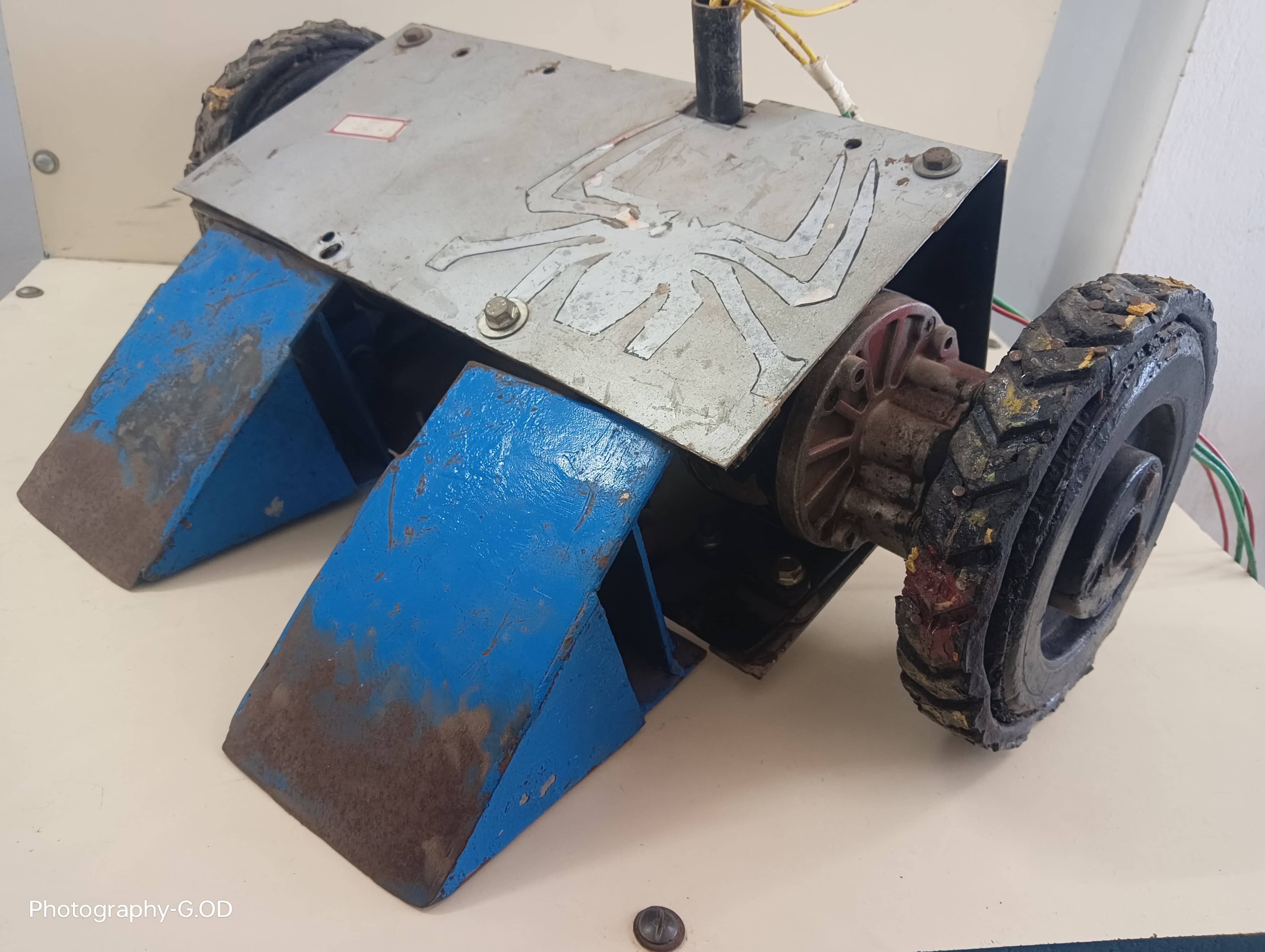
Project Overview
A competitive robot designed for robotics combat competitions with enhanced durability and tactical features.
Technical Analysis
Powered by NRC AIAs a robotics and electronics expert, I'm delighted to provide a comprehensive technical analysis for your "War Robot" project. This project is an excellent blend of mechanical design, power electronics, embedded programming, and control systems, making it highly educational for engineering students.
Project: War Robot (Competitive Combat Robotics)
article1. Technical Overview
The "War Robot" project is fundamentally about designing and building a remotely controlled vehicle capable of operating in a competitive combat environment. This involves robust mechanical design, high-power electrical systems, and precise control logic.
- Core Functionality: The robot's primary functions include mobility (driving) and an offensive/defensive mechanism (weapon). Control is typically achieved via a radio-frequency (RF) remote control system.
- Mechanical Systems:
- Chassis: Designed for extreme durability, often using materials like aluminum, steel, titanium, or high-density plastics (e.g., HDPE, polycarbonate). It must protect internal components from impacts and house the drivetrain and weapon system.
- Drivetrain: Usually consists of powerful DC brushed or brushless motors driving wheels or tracks. A common configuration is a 2-wheel or 4-wheel drive system (skid-steer/tank drive) for maneuverability. Gearboxes are crucial to convert high RPM, low-torque motor output into lower RPM, high-torque suitable for movement.
- Weapon System: This is the robot's offensive capability. Common types include:
- Spinners/Vertical Disc Spinners: High-speed rotating mass (blade, bar, drum) to impart kinetic energy.
- Flippers/Lifters: Pneumatic or motor-driven mechanisms to throw opponents.
- Wedges: Low-profile, armored ramps to get under opponents.
- Hammers: Impact weapons.
- Electrical Systems:
- Power Supply: High-discharge Lithium Polymer (LiPo) batteries are standard due to their excellent power-to-weight ratio. Robust wiring, connectors, and fuses are essential for safety and reliability under high current loads. A main "kill switch" is mandatory for emergency power cutoff.
- Motor Control: High-current motor drivers (H-bridges, Electronic Speed Controllers - ESCs) convert low-power control signals from the microcontroller into high-power signals to drive the motors.
- Logic Control: A microcontroller (e.g., Arduino, ESP32, Teensy) acts as the brain. It receives commands from the RC receiver, processes them, and sends appropriate signals to the motor drivers and weapon actuators.
- Control System:
- Remote Control (RC): A standard 2.4 GHz hobby RC transmitter and receiver pair is used. The receiver outputs PWM (Pulse Width Modulation) signals corresponding to joystick positions and switch states.
- Software Logic: The microcontroller interprets these PWM signals to control the robot's speed, direction (tank drive mixing), and weapon activation.
- Durability & Tactics: "Enhanced durability" implies robust component selection, strategic armor placement, and potentially redundant systems. "Tactical features" could range from basic defensive geometry (wedge) to more advanced elements like current/voltage monitoring for power management, or even rudimentary autonomous obstacle avoidance (though less common in pure combat for simplicity and weight).
article2. Components Required
Here's a comprehensive list of components, assuming a 4-wheel drive (skid-steer) robot with a powerful spinning weapon controlled by an Arduino Mega.
label_importantA. Electronic Components
- Microcontroller Board:
- Arduino Mega 2560: Offers ample digital I/O pins, analog input pins, and multiple hardware serial ports. Ideal for handling multiple motor drivers, RC channels, and potential sensors.
- Motor Drivers:
- For Drive Motors (x2): High-current Dual Brushed DC Motor Drivers.
- Example: Cytron MDD10A (10A continuous, 30A peak) or Pololu G2 High-Power Motor Driver 24v13 (13A continuous, 30A peak, single channel - would need 4 of these or 2 dual drivers). For this guide, we'll assume two MDD10A boards, each controlling two motors on one side of the robot (left/right).
- For Weapon Motor (x1): A dedicated high-current motor driver or an ESC (if using a brushless weapon motor).
- Example: Cytron MDD10A (if weapon is brushed DC) or Brushless ESC (e.g., 80A-120A, for drone/RC car applications) if using a brushless motor. We'll stick with a brushed DC weapon motor for simplicity.
- For Drive Motors (x2): High-current Dual Brushed DC Motor Drivers.
- Power Supply:
- LiPo Battery (x1-2): High discharge rate (e.g., 3S or 4S, 30C+), capacity suitable for expected run time (e.g., 2000-5000 mAh).
- Battery Charger: Compatible with LiPo batteries (balance charger).
- Battery Eliminator Circuit (BEC) / Voltage Regulator: Step-down module (e.g., Buck converter) to provide stable 5V or 6V for the Arduino and RC receiver from the LiPo battery. (e.g., UBEC 5V/3A).
- Communication:
- 2.4 GHz RC Transmitter & Receiver (4+ Channels): Standard hobby-grade RC system (e.g., FlySky FS-i6X with FS-iA6B receiver).
- Safety & Wiring:
- Main Kill Switch (Heavy Duty): Large, easily accessible switch to cut all power (e.g., 100A rated toggle switch).
- Inline Blade Fuses / Circuit Breakers: For main power line and possibly individual motor lines (e.g., 30A-60A for main, 15A-20A for motors).
- High-Gauge Silicone Wire: 12-14 AWG for main power, 16-18 AWG for motor connections, 22-24 AWG for signal wires.
- XT60/XT90/Deans Connectors: For battery connections.
- Jumper Wires: Male-to-male, male-to-female.
- Heat Shrink Tubing: For insulation.
- Cable Ties / Wire Loom: For cable management.
label_importantB. Sensors (Optional, for "Tactical Features")
- ACS712 Current Sensor (x2-3): To monitor current draw of drive motors and/or weapon motor, or main battery. (e.g., ACS712 30A module).
- Voltage Divider Circuit: To monitor battery voltage level.
- IR Distance Sensor (x1-2): For basic obstacle detection or opponent proximity (e.g., VL53L0X or Sharp IR sensor). Less common in pure combat, but adds "tactical" element.
label_importantC. Actuators
- Drive Motors (x4): High-torque brushed DC gearmotors (e.g., BaneBots RS-550 with P60 gearboxes, or NEMA 17/23 stepper motors used as DC motors for robustness and high torque). Match kV/RPM to desired speed and torque.
- Weapon Motor (x1): High-power brushed DC motor (e.g., larger RS-550, or modified power tool motor), or a powerful brushless motor.
label_importantD. Mechanical Components & Materials
- Chassis Materials:
- Sheet Aluminum (6061-T6): 1/8" to 1/4" thick for structural elements.
- HDPE/UHMW/Polycarbonate: For armor plating, internal mounting.
- Steel/Titanium: For weapon components, high-impact areas.
- Wheels (x4): Rubber or foam wheels, designed for traction and durability.
- Weapon Mechanism:
- Steel Bar/Disc/Drum: For spinners. Precision machined and balanced.
- Bearings: High-speed, robust bearings for weapon shafts.
- Shafts/Pulleys/Belts/Gears: For power transmission to the weapon.
- Fasteners: M3, M4, M5 bolts, nuts, washers (nyloc nuts recommended).
- Standoffs: For mounting PCBs.
- Mounting Brackets: For motors, battery.
label_importantE. Tools
- Soldering Iron & Solder: For robust electrical connections.
- Wire Strippers & Crimpers: For wire preparation and connector crimping.
- Multimeter: Essential for testing voltage, current, continuity.
- Heat Gun: For heat shrink tubing.
- Basic Hand Tools: Screwdrivers, wrenches, pliers, cutters.
- Power Tools (for fabrication): Drill press, angle grinder, band saw, Dremel (depending on complexity).
- Safety Gear: Safety glasses, gloves.
article3. Circuit Diagram Description
This description assumes an Arduino Mega 2560, two Cytron MDD10A dual motor drivers (one for left drive, one for right drive), and one MDD10A for the weapon.
Overall Power Flow:
- LiPo Battery: Main power source.
- Main Kill Switch: Connected in series with the positive terminal of the LiPo battery. This is the primary safety cutoff.
- Main Fuse: Connected in series after the kill switch, before any power distribution. Protects against catastrophic short circuits.
- Power Distribution Hub: From the main fuse, power splits to:
- Drive Motor Drivers (MDD10A x2): Each MDD10A board has terminals for (battery voltage) and
V_IN.GND - Weapon Motor Driver (MDD10A x1): Similar and
V_INterminals.GND - BEC/Voltage Regulator: To step down LiPo voltage (e.g., 11.1V-14.8V) to 5V for the Arduino and RC receiver.
- Drive Motor Drivers (MDD10A x2): Each MDD10A board has terminals for
Detailed Connections:
-
LiPo Battery:
- Positive (+) terminal to Main Kill Switch IN.
- Negative (-) terminal to Common Ground (GND) rail.
-
Main Kill Switch:
- of kill switch to Main Fuse IN.
OUT
-
Main Fuse:
- of fuse to positive
OUTterminals of all MDD10A boards and the BEC/Voltage Regulator.V_IN
-
BEC/Voltage Regulator:
- to fused LiPo positive.
V_IN - to Common Ground.
GND - (5V) to Arduino Mega's
V_OUTpin (or5Vif it's a 7-12V regulator) and the RC Receiver'sVINpin.VCC - from BEC to Arduino Mega's
GNDand RC Receiver'sGND.GND
-
Arduino Mega 2560:
- (or
5Vdepending on BEC type) connected to BEC'sVIN.V_OUT - connected to BEC's
GNDand Common Ground.GND
-
RC Receiver (e.g., FlySky FS-iA6B):
- Power: to BEC's
VCC(5V),V_OUTto BEC'sGND.GND - Signal Pins (PWM Output):
- Channel 1 (Aileron/Roll - often for turning): Connect to Arduino Digital Pin 2.
- Channel 2 (Elevator/Pitch - often for forward/reverse): Connect to Arduino Digital Pin 3.
- Channel 3 (Throttle - often for weapon): Connect to Arduino Digital Pin 4.
- Channel 4 (Rudder/Yaw - often for weapon safety/enable): Connect to Arduino Digital Pin 5.
- (Note: Pin numbers are arbitrary, but choose interrupt-capable pins if possible for if other operations might block; for simple reading, any digital pin works).
pulseIn
- Power:
-
Motor Drivers (MDD10A x3): Each MDD10A controls two motors (or one motor if using only one channel). Each has:
- : Connect to fused LiPo positive.
V_IN - : Connect to Common Ground.
GND - Control Pins (from Arduino):
- (PWM signal for Motor 1 speed)
M1_PWM - (Digital signal for Motor 1 direction)
M1_DIR - (PWM signal for Motor 2 speed)
M2_PWM - (Digital signal for Motor 2 direction)
M2_DIR
- Motor Output Terminals:
- ,
M1A: Connect to Drive Motor 1.M1B - ,
M2A: Connect to Drive Motor 2.M2B
Specific Pin Assignments (Example):
-
Left Drive Motors (controlled by MDD10A_1):
- (MDD10A_1) -> Arduino Pin 6 (PWM)
M1_PWM - (MDD10A_1) -> Arduino Pin 7 (Digital)
M1_DIR - (MDD10A_1) -> Arduino Pin 8 (PWM)
M2_PWM - (MDD10A_1) -> Arduino Pin 9 (Digital)
M2_DIR - Motors M1, M2 connected to respective outputs.
-
Right Drive Motors (controlled by MDD10A_2):
- (MDD10A_2) -> Arduino Pin 10 (PWM)
M1_PWM - (MDD10A_2) -> Arduino Pin 11 (Digital)
M1_DIR - (MDD10A_2) -> Arduino Pin 12 (PWM)
M2_PWM - (MDD10A_2) -> Arduino Pin 13 (Digital)
M2_DIR - Motors M3, M4 connected to respective outputs.
-
Weapon Motor (controlled by MDD10A_3):
- (MDD10A_3) -> Arduino Pin 44 (PWM)
M1_PWM - (MDD10A_3) -> Arduino Pin 45 (Digital)
M1_DIR - (M2 outputs left unused, or can power a second small weapon/utility motor).
- Weapon Motor connected to M1 outputs.
-
Sensors (Optional - Example for ACS712 Current Sensor):
- (ACS712) -> Arduino
VCC(or directly from BEC).5V - (ACS712) -> Arduino
GND.GND - (ACS712) -> Arduino Analog Pin A0 (for main battery current) or A1, A2 for individual motors.
V_OUT
Wiring Considerations:
- Heavy Gauge Wires: Use appropriate wire gauge for high-current paths (battery to motor drivers). Undersized wires will heat up and cause voltage drop.
- Soldered Connections: Prefer soldered connections for all high-current paths for reliability. Use heat shrink for insulation.
- Proper Grounding: Ensure all GNDs (battery, motor drivers, Arduino, receiver, sensors) are connected to a common ground point.
- Ferrite Beads/Capacitors: Consider adding ferrite beads on signal lines or capacitors across motor terminals to reduce electrical noise, which can interfere with the microcontroller and RC signals.
- Mounting: Secure all electronic components firmly to the chassis using standoffs or double-sided tape, especially in a combat robot where heavy impacts are expected.
article4. Source Code
This code provides a basic framework for controlling a 4-wheel drive tank robot with a spinning weapon. It assumes standard PWM input from an RC receiver (1000-2000us pulse width, ~1500us center).
Programming Language: Arduino C++
C++// ============================================================================= // Project: War Robot Control // Author: Your Name / Robotics Expert // Date: Oct 26, 2023 // Description: // This code controls a competitive combat robot with a 4-wheel skid-steer // drivetrain and a single spinning weapon. It reads PWM signals from an // RC receiver and translates them into motor commands for drive and weapon. // Includes safety features for the weapon. // // Hardware Assumptions: // - Arduino Mega 2560 // - Two Cytron MDD10A Dual Motor Drivers for drive (Left & Right side) // - One Cytron MDD10A Dual Motor Driver for weapon // - 2.4 GHz RC Receiver with PWM outputs for at least 4 channels // - High-torque brushed DC motors for drive and weapon // - LiPo battery with BEC for 5V logic power // // RC Channel Mapping (Example): // - CH1 (Roll): Left/Right Movement (Turning) // - CH2 (Pitch): Forward/Backward Movement (Drive) // - CH3 (Throttle): Weapon Motor Speed/Activation // - CH4 (Yaw/Aux1): Weapon Safety Toggle (High = ON, Low = OFF) // // Motor Driver MDD10A Control Logic: // - M1_PWM, M1_DIR for Motor 1 // - M2_PWM, M2_DIR for Motor 2 // - PWM input (0-255) controls speed. // - DIR input (HIGH/LOW) controls direction. // ============================================================================= // --- Libraries --- // No specific libraries required beyond standard Arduino functions for pulseIn and analogWrite. // --- Pin Definitions --- // RC Receiver Input Pins (using pulseIn for these) const int RC_CHANNEL_ROLL_PIN = 2; // CH1: Left/Right turning const int RC_CHANNEL_PITCH_PIN = 3; // CH2: Forward/Backward drive const int RC_CHANNEL_THROTTLE_PIN = 4; // CH3: Weapon speed const int RC_CHANNEL_AUX1_PIN = 5; // CH4: Weapon Safety Enable (High = ON) // Drive Motor Driver 1 (Left Side Drivetrain) const int L_DRIVE_M1_PWM_PIN = 6; // Left Front Motor PWM const int L_DRIVE_M1_DIR_PIN = 7; // Left Front Motor Direction const int L_DRIVE_M2_PWM_PIN = 8; // Left Rear Motor PWM const int L_DRIVE_M2_DIR_PIN = 9; // Left Rear Motor Direction // Drive Motor Driver 2 (Right Side Drivetrain) const int R_DRIVE_M1_PWM_PIN = 10; // Right Front Motor PWM const int R_DRIVE_M1_DIR_PIN = 11; // Right Front Motor Direction const int R_DRIVE_M2_PWM_PIN = 12; // Right Rear Motor PWM const int R_DRIVE_M2_DIR_PIN = 13; // Right Rear Motor Direction // Weapon Motor Driver (e.g., MDD10A controlling one motor) const int WEAPON_PWM_PIN = 44; // Weapon Motor PWM const int WEAPON_DIR_PIN = 45; // Weapon Motor Direction (can be tied HIGH for single-direction weapon) // Sensor Pins (Optional - uncomment and configure if used) // const int BATTERY_CURRENT_PIN = A0; // ACS712 for main battery current // const int BATTERY_VOLTAGE_PIN = A1; // Voltage divider for battery voltage // --- Global Variables --- // RC input pulse widths int rcRollPulse = 0; int rcPitchPulse = 0; int rcThrottlePulse = 0; int rcAux1Pulse = 0; // Mapped motor speeds (-255 to 255 for direction, 0 to 255 for PWM) int leftDriveSpeed = 0; int rightDriveSpeed = 0; int weaponSpeed = 0; bool weaponEnabled = false; // Safety flag for weapon // Configuration for RC pulse mapping const int RC_MIN_PULSE = 1000; // Minimum pulse width (microseconds) const int RC_MAX_PULSE = 2000; // Maximum pulse width (microseconds) const int RC_CENTER_PULSE = 1500; // Center pulse width (microseconds) const int RC_DEADBAND = 50; // Deadband for joystick inputs around center (e.g., +/- 50us) // --- Function Prototypes --- void readRCInputs(); void calculateDriveSpeeds(); void controlDriveMotors(int leftSpeed, int rightSpeed); void controlWeaponMotor(int speed); int mapRCtoMotor(int rcPulse, int deadband); // Maps RC pulse to motor speed (-255 to 255) // --- Setup Function --- void setup() { Serial.begin(9600); // Initialize serial communication for debugging // Configure RC input pins pinMode(RC_CHANNEL_ROLL_PIN, INPUT); pinMode(RC_CHANNEL_PITCH_PIN, INPUT); pinMode(RC_CHANNEL_THROTTLE_PIN, INPUT); pinMode(RC_CHANNEL_AUX1_PIN, INPUT); // Configure Drive Motor Driver Pins pinMode(L_DRIVE_M1_PWM_PIN, OUTPUT); pinMode(L_DRIVE_M1_DIR_PIN, OUTPUT); pinMode(L_DRIVE_M2_PWM_PIN, OUTPUT); pinMode(L_DRIVE_M2_DIR_PIN, OUTPUT); pinMode(R_DRIVE_M1_PWM_PIN, OUTPUT); pinMode(R_DRIVE_M1_DIR_PIN, OUTPUT); pinMode(R_DRIVE_M2_PWM_PIN, OUTPUT); pinMode(R_DRIVE_M2_DIR_PIN, OUTPUT); // Configure Weapon Motor Driver Pins pinMode(WEAPON_PWM_PIN, OUTPUT); pinMode(WEAPON_DIR_PIN, OUTPUT); // Ensure all motors are off at start controlDriveMotors(0, 0); controlWeaponMotor(0); // For weapon motor that only spins one direction, set DIR pin once // digitalWrite(WEAPON_DIR_PIN, HIGH); // Example: always forward Serial.println("War Robot System Ready!"); } // --- Loop Function --- void loop() { readRCInputs(); // Read all RC channels // Update weapon safety state based on Aux1 channel // If Aux1 is high (e.g., > 1700us), weapon is enabled. weaponEnabled = (rcAux1Pulse > (RC_CENTER_PULSE + RC_DEADBAND)); calculateDriveSpeeds(); // Determine individual left/right drive speeds // Control Motors controlDriveMotors(leftDriveSpeed, rightDriveSpeed); // Control Weapon (only if enabled by safety switch) if (weaponEnabled) { // Map throttle channel to weapon speed (0-255) // Adjust mapping for throttle if it's 0-1000us instead of 1000-2000us center. // For a standard throttle, 1000us is min, 2000us is max. // So, map 1000-2000 to 0-255. weaponSpeed = map(rcThrottlePulse, RC_MIN_PULSE, RC_MAX_PULSE, 0, 255); // Ensure weapon speed is positive (spinners usually one direction) weaponSpeed = abs(weaponSpeed); controlWeaponMotor(weaponSpeed); } else { controlWeaponMotor(0); // Weapon off if not enabled } // --- Optional: Debugging Output --- /* Serial.print("RC Roll: "); Serial.print(rcRollPulse); Serial.print(" | Pitch: "); Serial.print(rcPitchPulse); Serial.print(" | Throttle: "); Serial.print(rcThrottlePulse); Serial.print(" | Aux1: "); Serial.print(rcAux1Pulse); Serial.print(" | L_Speed: "); Serial.print(leftDriveSpeed); Serial.print(" | R_Speed: "); Serial.print(rightDriveSpeed); Serial.print(" | Weapon Speed: "); Serial.print(weaponSpeed); Serial.print(" | Weapon Enabled: "); Serial.println(weaponEnabled ? "YES" : "NO"); */ delay(20); // Small delay to prevent too rapid updates and allow sensor readings (if implemented) } // --- Helper Functions --- /** * @brief Reads the pulse width from all configured RC input channels. */ void readRCInputs() { rcRollPulse = pulseIn(RC_CHANNEL_ROLL_PIN, HIGH, 25000); // 25ms timeout rcPitchPulse = pulseIn(RC_CHANNEL_PITCH_PIN, HIGH, 25000); rcThrottlePulse = pulseIn(RC_CHANNEL_THROTTLE_PIN, HIGH, 25000); rcAux1Pulse = pulseIn(RC_CHANNEL_AUX1_PIN, HIGH, 25000); } /** * @brief Maps an RC pulse width to a motor speed value (-255 to 255) with a deadband. * @param rcPulse The raw pulse width from the RC receiver. * @param deadband The width of the deadband around the center pulse. * @return Mapped motor speed value. */ int mapRCtoMotor(int rcPulse, int deadband) { int mappedValue = 0; if (rcPulse == 0) { // If no pulse detected (timeout), assume center/off mappedValue = 0; } else if (rcPulse >= (RC_CENTER_PULSE - deadband) && rcPulse <= (RC_CENTER_PULSE + deadband)) { mappedValue = 0; // Within deadband, motor is stopped } else if (rcPulse < RC_CENTER_PULSE) { // Reverse direction mappedValue = map(rcPulse, RC_MIN_PULSE, RC_CENTER_PULSE - deadband, -255, 0); } else { // Forward direction mappedValue = map(rcPulse, RC_CENTER_PULSE + deadband, RC_MAX_PULSE, 0, 255); } // Clamp values to ensure they are within the valid range mappedValue = constrain(mappedValue, -255, 255); return mappedValue; } /** * @brief Calculates left and right drive motor speeds based on RC Pitch (forward/backward) * and Roll (turning) inputs for tank drive. */ void calculateDriveSpeeds() { int pitchValue = mapRCtoMotor(rcPitchPulse, RC_DEADBAND); // Forward/Backward int rollValue = mapRCtoMotor(rcRollPulse, RC_DEADBAND); // Left/Right (turning) // Tank drive mixing (Arcade control scheme) leftDriveSpeed = pitchValue + rollValue; rightDriveSpeed = pitchValue - rollValue; // Clamp speeds to -255 to 255 to prevent overflow and ensure valid PWM range leftDriveSpeed = constrain(leftDriveSpeed, -255, 255); rightDriveSpeed = constrain(rightDriveSpeed, -255, 255); } /** * @brief Controls the speed and direction of the drive motors. * @param leftSpeed Speed for left side motors (-255 to 255). * @param rightSpeed Speed for right side motors (-255 to 255). */ void controlDriveMotors(int leftSpeed, int rightSpeed) { // Left Side Motors if (leftSpeed >= 0) { // Forward digitalWrite(L_DRIVE_M1_DIR_PIN, HIGH); digitalWrite(L_DRIVE_M2_DIR_PIN, HIGH); analogWrite(L_DRIVE_M1_PWM_PIN, leftSpeed); analogWrite(L_DRIVE_M2_PWM_PIN, leftSpeed); } else { // Reverse digitalWrite(L_DRIVE_M1_DIR_PIN, LOW); digitalWrite(L_DRIVE_M2_DIR_PIN, LOW); analogWrite(L_DRIVE_M1_PWM_PIN, abs(leftSpeed)); analogWrite(L_DRIVE_M2_PWM_PIN, abs(leftSpeed)); } // Right Side Motors if (rightSpeed >= 0) { // Forward digitalWrite(R_DRIVE_M1_DIR_PIN, HIGH); digitalWrite(R_DRIVE_M2_DIR_PIN, HIGH); analogWrite(R_DRIVE_M1_PWM_PIN, rightSpeed); analogWrite(R_DRIVE_M2_PWM_PIN, rightSpeed); } else { // Reverse digitalWrite(R_DRIVE_M1_DIR_PIN, LOW); digitalWrite(R_DRIVE_M2_DIR_PIN, LOW); analogWrite(R_DRIVE_M1_PWM_PIN, abs(rightSpeed)); analogWrite(R_DRIVE_M2_PWM_PIN, abs(rightSpeed)); } } /** * @brief Controls the speed and direction of the weapon motor. * @param speed Speed for weapon motor (0 to 255, assuming unidirectional spinner). */ void controlWeaponMotor(int speed) { // For a unidirectional spinner, set DIR pin once in setup (e.g., HIGH) // and only vary PWM. If it can spin both ways, use similar logic as drive motors. digitalWrite(WEAPON_DIR_PIN, HIGH); // Assuming weapon always spins "forward" analogWrite(WEAPON_PWM_PIN, constrain(speed, 0, 255)); } // --- Optional Sensor Reading Functions (uncomment and integrate if using) --- /* float readBatteryCurrent() { // Assuming ACS712 30A module, sensitivity is 66mV/A, VCC=5V -> 2.5V at 0A int sensorValue = analogRead(BATTERY_CURRENT_PIN); float voltage = sensorValue * (5.0 / 1023.0); // Convert raw sensor reading to voltage float current = (voltage - 2.5) / 0.066; // Calculate current (Amps) Serial.print("Current: "); Serial.print(current); Serial.println("A"); return current; } float readBatteryVoltage() { // Assuming a voltage divider (e.g., 10k and 2k resistors for 3S/4S LiPo) // Vin = Vout * (R1 + R2) / R2 int sensorValue = analogRead(BATTERY_VOLTAGE_PIN); float voltage = sensorValue * (5.0 / 1023.0); // Voltage at analog pin // Adjust the multiplier based on your voltage divider's ratio // E.g., if divider ratio is 1/5, actual battery voltage = voltage * 5 float batteryVoltage = voltage * (10.0 + 2.0) / 2.0; // Example for 12V max, 1/6 divider Serial.print("Battery Voltage: "); Serial.print(batteryVoltage); Serial.println("V"); return batteryVoltage; } */
article5. Source Code Structure
The provided source code is structured for clarity and maintainability, which is crucial for complex robotics projects.
- Header/Comments: Extensive comments at the beginning explain the project, hardware assumptions, RC channel mapping, and motor driver logic. This is vital for documentation and understanding.
- Libraries Needed:
- Standard Arduino Library: The code primarily uses standard Arduino functions like ,
pinMode(),digitalWrite(),analogWrite(),pulseIn(),map(),constrain(),abs(),Serial.begin(),Serial.print(). No special third-party libraries are explicitly required for this basic functionality.Serial.println()
- Standard Arduino Library: The code primarily uses standard Arduino functions like
- Pin Definitions:
- All hardware I/O pins are defined as at the top. This makes it easy to change pin assignments without searching through the code and improves readability.
const int
- All hardware I/O pins are defined as
- Global Variables:
- Variables that need to be accessed across multiple functions (like ,
rcRollPulse,leftDriveSpeed) are declared globally.weaponEnabled - Configuration constants (e.g., ,
RC_MIN_PULSE) are also defined globally for easy tuning.RC_DEADBAND
- Variables that need to be accessed across multiple functions (like
- Function Prototypes:
- All custom functions (,
readRCInputs,calculateDriveSpeeds,controlDriveMotors,controlWeaponMotor) are declared beforemapRCtoMotorandsetup(). This helps the compiler and improves code organization.loop()
- All custom functions (
- Function:
setup()- Executed once at the start of the Arduino board.
- Initializes serial communication for debugging.
- Sets up all input and output pin modes.
- Ensures all motors are off by calling control functions with zero speed.
- Prints a "System Ready" message to the serial monitor.
- Function:
loop()- The main execution loop, runs continuously after .
setup() - Reads RC Inputs: Calls to get the latest joystick and switch states.
readRCInputs() - Weapon Safety Logic: Checks the (safety switch) to enable/disable the weapon. This is a critical safety feature.
RC_CHANNEL_AUX1_PIN - Calculates Drive Speeds: Calls to mix the RC inputs into left and right motor speeds for tank drive.
calculateDriveSpeeds() - Controls Drive Motors: Calls to set the power and direction of the drivetrain.
controlDriveMotors() - Controls Weapon Motor: Calls only if the weapon safety is enabled, mapping the throttle input to weapon speed.
controlWeaponMotor() - Debugging Output (Commented): Includes optional serial print statements for monitoring variable values, which are invaluable during testing and debugging.
- Delay: A small delay to prevent the loop from running too fast, which can sometimes lead to instability or prevent accurate readings.
pulseIn
- The main execution loop, runs continuously after
- Key Functions:
- : Uses
readRCInputs()to measure the duration of the HIGH pulse from each RC channel, which corresponds to joystick position or switch state.pulseIn() - : A crucial utility function that takes a raw RC pulse width (e.g., 1000-2000us) and maps it to a motor control value (e.g., -255 to 255). It includes a
mapRCtoMotor(int rcPulse, int deadband)around the center to prevent motors from twitching when the joystick is near neutral.deadband - : Implements the tank drive (arcade drive) mixing logic. It combines the forward/backward input (pitch) and turning input (roll) to determine the individual speeds for the left and right motor sets.
calculateDriveSpeeds() - : Takes the calculated speeds for the left and right sides. For each side, it determines the direction (forward/reverse) by setting the
controlDriveMotors(int leftSpeed, int rightSpeed)pin (HIGH/LOW) and then applies the absolute speed value to theDIRpin usingPWM.analogWrite() - : Controls the weapon motor. For a unidirectional spinner, it simply sets the direction once (e.g., HIGH) and uses
controlWeaponMotor(int speed)for speed.analogWrite() - /
readBatteryCurrent(): (Commented out but provided as examples) These functions demonstrate how to read data from sensors connected to analog input pins and convert them into meaningful physical units.readBatteryVoltage()
article6. Step-by-Step Implementation Guide
This guide assumes you have all components and tools ready.
label_importantA. Hardware Assembly Steps
Safety First: Always disconnect the battery when working on wiring or mechanical assembly. Wear safety glasses when cutting, drilling, or handling sharp parts.
- Chassis Fabrication & Drivetrain Mounting:
- Cut Chassis Pieces: Cut the base plate, side armor, and internal mounting plates from your chosen materials (aluminum, HDPE). Drill mounting holes for motors, wheels, and electronics.
- Assemble Drivetrain: Mount the 4 drive motors to the chassis (2 on each side). Ensure they are aligned for proper wheel tracking.
- Attach Wheels: Securely attach the wheels to the motor shafts. Ensure proper spacing for clearance.
- Mount Armor: Attach side and front/rear armor plates. Use robust fasteners (nyloc nuts, threadlock) to prevent loosening from vibration and impacts.
- Weapon System Assembly:
- Mount Weapon Motor: Securely mount the weapon motor. Consider using a dedicated bracket or internal frame for rigidity.
- Shaft & Bearings: Mount the weapon shaft, ensuring it runs smoothly on robust bearings.
- Attach Weapon Element: Securely attach the spinning bar/disc/drum to the weapon shaft. Crucially, ensure the weapon is balanced to prevent catastrophic vibration at high speeds. This may require professional balancing.
- Power Transmission: Install pulleys/gears/belts if using a reduction system from the motor to the weapon shaft.
- Electronics Mounting:
- BEC/Voltage Regulator: Mount the BEC securely, preferably on an insulated surface to prevent short circuits.
- Arduino Mega: Mount the Arduino board using plastic standoffs to prevent it from touching the metal chassis.
- Motor Drivers: Mount the MDD10A boards. Ensure good airflow if possible, as they can get warm under load. Consider heatsinks if not built-in.
- RC Receiver: Mount the RC receiver in a location that provides good signal reception and is protected from impacts. Ensure antennas are correctly oriented and not obstructed by metal.
- Battery Tray: Design and build a secure battery tray or compartment. The battery must be held very firmly to prevent dislodging during impacts.
- Kill Switch: Mount the main kill switch in an easily accessible location on the exterior of the robot.
- Fuses: Mount fuse holders for inline blade fuses.
- Wiring:
- High-Current Wiring (Battery to Motors/Drivers):
- Connect LiPo battery to the Kill Switch IN.
- Connect Kill Switch OUT to the Main Fuse IN.
- Connect Main Fuse OUT to the of all motor drivers and the
V_INof the BEC. Use heavy gauge wire (12-14 AWG) and robust connectors (XT60/XT90).V_IN - Connect the of the LiPo to a common ground point, and connect
GNDfrom all motor drivers and the BEC to this common ground.GND - Connect motor driver outputs (,
M1A/B) to their respective motors using 16-18 AWG wire. Pay attention to polarity for direction, but this can be corrected in software or by swapping wires.M2A/B
- Low-Current/Signal Wiring (Arduino, RC Receiver, Sensors):
- Connect BEC (5V) to Arduino Mega
V_OUTpin and RC Receiver5V. Connect BECVCCto ArduinoGNDand RC ReceiverGND.GND - Connect RC Receiver PWM signal pins (CH1-CH4) to Arduino Digital Pins (2, 3, 4, 5).
- Connect Arduino Digital Pins (6-13, 44-45) to the and
PWMcontrol pins of the respective motor drivers.DIR - (Optional) Connect sensor /
VCCto ArduinoGND/5V, and sensorGNDto Arduino Analog Pins (V_OUT,A0, etc.).A1
- Connect BEC
- Cable Management: Use cable ties, wire loom, and heat shrink to keep wires organized, protected, and away from moving parts.
- High-Current Wiring (Battery to Motors/Drivers):
label_importantB. Software Setup and Programming
- Install Arduino IDE: Download and install the latest Arduino IDE from the official Arduino website.
- Board Support Package: In Arduino IDE, go to and ensure "Arduino AVR Boards" are installed. Select "Arduino Mega 2560" under
Tools > Board > Boards Manager....Tools > Board > Arduino AVR Boards - Copy Source Code: Copy the provided C++ source code into a new Arduino sketch.
- Verify & Upload:
- Connect your Arduino Mega to your computer via USB.
- Select the correct serial port under .
Tools > Port - Click the "Verify" (checkmark icon) button to compile the code and check for errors.
- Click the "Upload" (right arrow icon) button to upload the compiled code to the Arduino Mega.
label_importantC. Testing and Calibration Procedures
ALWAYS perform testing with the robot off the ground or with the weapon disabled and disarmed.
- Initial Power-Up and RC Link:
- Ensure all motors are disconnected or the robot is safely supported.
- Turn on your RC Transmitter first.
- Connect the LiPo battery to the robot (or toggle the kill switch to ON). The Arduino should power up, and the RC receiver should link with the transmitter (usually indicated by an LED).
- Do not enable the weapon yet.
- Motor Direction and Speed Calibration (Drive):
- Open the Arduino IDE's Serial Monitor ().
Tools > Serial Monitor - Uncomment the debugging lines in the
Serial.printfunction.loop() - Observe the and
rcPitchPulsevalues as you move the joysticks. Confirm they range from ~1000us to ~2000us with ~1500us at center.rcRollPulse - Move the Pitch joystick forward. Observe and
leftDriveSpeed. They should be positive and increase.rightDriveSpeed - Move the Pitch joystick backward. Speeds should be negative.
- Move the Roll joystick left/right. Observe how and
leftDriveSpeedchange (one should increase, the other decrease for turning).rightDriveSpeed - Test Motors: With the robot safely raised, slowly move the Pitch joystick forward.
- Verify all 4 drive motors spin in the correct direction (e.g., all forward when joystick forward).
- If a motor spins backward, you can either swap its two wires going to the motor driver output, or change the logic in
DIRfor that specific motor (e.g.,controlDriveMotors()for forward if you need to invert).digitalWrite(L_DRIVE_M1_DIR_PIN, LOW) - Verify motors stop when joysticks are centered (due to deadband).
- Test turning: push Pitch forward slightly, then Roll left/right. Verify the robot turns as expected.
- Open the Arduino IDE's Serial Monitor (
- Weapon Motor Calibration:
- Crucial Safety Step: If your weapon is a spinner, remove the spinning bar/disc/drum from the shaft or ensure it cannot move or cause harm.
- Verify changes when you toggle the weapon safety switch on your RC transmitter.
rcAux1Pulse - Verify variable correctly reflects the switch state.
weaponEnabled - With the weapon safety enabled, slowly move the Throttle joystick.
- Observe in the serial monitor. It should range from 0 to 255.
weaponSpeed - Verify the weapon motor spins as throttle increases. Ensure it spins in the desired direction. Adjust logic in
WEAPON_DIR_PINor wiring if needed.controlWeaponMotor() - Verify the motor stops when throttle is at minimum or weapon safety is disabled.
- Overall System Test:
- Place the robot on the ground in a safe, open area.
- Perform full range-of-motion tests for driving (forward, reverse, turns).
- Test weapon activation and deactivation.
- Do not operate the weapon at full speed or near people/fragile objects until fully confident in its safety and control.
- Check for any unexpected behavior, motor stalling, or excessive heat.
- Final Safety Check:
- Test the main kill switch repeatedly. It must immediately cut all power.
- Ensure all fasteners are tight.
- Check for any loose wires or components.
article7. Challenges and Solutions
Engineering students commonly face several challenges in "War Robot" projects:
-
Challenge: Power Management (High Current Draw & Voltage Drop)
- Problem: Motors, especially during stalls or impacts, draw huge current spikes (tens to hundreds of amps). This can cause significant voltage drop, leading to brownouts (microcontroller resetting), motor driver damage, or battery damage.
- Solution:
- Proper Battery Sizing: Use LiPo batteries with high C-ratings (discharge rate) and sufficient capacity.
- Heavy Gauge Wiring: Use appropriate wire thickness (AWG) for all high-current paths.
- Robust Connectors: XT60/XT90/Deans connectors are designed for high current.
- Fuses/Circuit Breakers: Protect against overcurrent and short circuits.
- Separate Power Rails: Use a dedicated BEC/voltage regulator for the microcontroller and RC receiver to isolate them from motor noise and voltage fluctuations.
- Capacitors: Add large electrolytic capacitors (e.g., 1000uF+) across the power inputs of motor drivers to help smooth out current spikes.
- Motor Driver Selection: Use drivers explicitly rated for the peak current draw of your motors.
-
Challenge: Mechanical Durability & Weight Limits
- Problem: Robots take massive impacts. Components can break, chassis can bend, and fasteners can loosen. Weight limits are strict in competitions.
- Solution:
- Material Selection: Use strong, impact-resistant materials (aluminum alloys, steel, titanium, high-density plastics like HDPE/UHMW) strategically.
- Design for Impact: Design the chassis to deflect blows, distribute forces, and protect vulnerable internal components. Use internal bracing.
- Secure Fasteners: Use nyloc nuts, thread-locking compounds, or lock washers to prevent bolts from vibrating loose.
- Component Mounting: Mount electronics using standoffs or flexible adhesive (e.g., silicone caulk) to absorb shock. Batteries must be rigidly secured.
- Weight Management: Plan your component choices and material thicknesses carefully from the start to stay within the weight limit. Optimize designs for minimum material use while maintaining strength.
-
Challenge: Electrical Noise and Interference
- Problem: High-current switching from motor drivers creates significant electromagnetic interference (EMI) that can disrupt RC signals or microcontroller operation.
- Solution:
- Ferrite Beads: Place ferrite beads on motor power lines and potentially signal lines to suppress noise.
- Capacitors on Motors: Add small ceramic capacitors (e.g., 0.1uF) across motor terminals and from each terminal to the motor case (if grounded) to filter noise.
- Separation: Keep high-current wires physically separate from low-current signal wires and RC receiver antennas.
- Shielding: Use shielded cables for sensitive signal lines if necessary.
- Grounding: Ensure a robust common ground plane for all components.
-
Challenge: Weapon Balancing & Vibration
- Problem: High-speed spinning weapons must be perfectly balanced. An unbalanced weapon will cause extreme vibrations, leading to premature bearing failure, component loosening, chassis fatigue, and dangerous operation.
- Solution:
- Precision Machining: Have the weapon component professionally machined to high tolerances.
- Dynamic Balancing: Get the weapon dynamically balanced by a specialist. This is often the most critical and overlooked step.
- Robust Bearings: Use high-quality, high-speed bearings designed for impact loads.
- Rigid Mounting: Mount the weapon motor and shaft assembly very rigidly to the chassis.
-
Challenge: Software Bugs and Debugging
- Problem: Incorrect logic, timing issues, or misconfigurations can lead to unpredictable robot behavior.
- Solution:
- Modular Code: Break down the code into small, testable functions (as provided in the example).
- Serial Debugging: Use extensively to monitor variable values, RC inputs, and motor outputs during testing.
Serial.print() - Incremental Development: Test each subsystem (drivetrain, weapon) individually before integrating them.
- Clear Pin Definitions: Define all pins at the top of the code for easy verification against the hardware.
- Deadbands & Constrain: Implement deadbands for joystick inputs and values to valid ranges to prevent unintended motor activation or erratic behavior.
constrain()
article8. Learning Outcomes
Undertaking the "War Robot" project provides invaluable learning experiences for engineering students across multiple disciplines:
- Mechanical Design and Fabrication:
- Understanding stress, strain, and material properties in impact scenarios.
- Design for manufacturability (DFM) and assembly.
- Precision drilling, cutting, and fastening techniques.
- Drivetrain mechanics (gearing, torque, speed, traction).
- Bearing selection and shaft design.
- Power Electronics and Electrical Systems:
- Fundamentals of high-current DC motor control (H-bridges, PWM).
- LiPo battery safety, charging, and management.
- Voltage regulation (BECs) and power distribution.
- Wiring practices, gauge selection, and connector choice for high-power applications.
- Importance of fuses, kill switches, and electrical safety.
- Noise suppression techniques (capacitors, ferrite beads).
- Embedded Systems and Microcontroller Programming:
- Interfacing with microcontrollers (Arduino I/O, analog/digital pins).
- Reading sensor inputs (,
pulseIn()).analogRead() - Generating control outputs (,
analogWrite()).digitalWrite() - Implementing control algorithms (tank drive mixing, deadbands).
- Structuring code for readability, maintainability, and debugging.
- Understanding real-time control concepts.
- System Integration and Troubleshooting:
- The complex interplay between mechanical, electrical, and software components.
- Systematic debugging of multi-domain problems (e.g., diagnosing a motor issue as either mechanical binding, electrical short, or software logic error).
- Iterative design and testing processes.
- Project Management and Teamwork:
- Planning, budgeting, and resource allocation.
- Time management and meeting deadlines.
- Collaboration, communication, and division of labor (if done in teams).
- Safety Awareness:
- Developing a strong sense of safety protocols when working with high-power electrical systems, fast-moving machinery, and sharp objects.
- Understanding the importance of emergency stops and failsafes.
article9. Extensions and Improvements
This project serves as an excellent foundation. Here are numerous ways to enhance it:
- Advanced Weapon Systems:
- Brushless Motors for Weapons: Use high-power brushless motors with appropriate ESCs for even higher weapon speeds and efficiency. Requires more complex ESC configuration.
- Pneumatic Flippers/Hammers: Integrate compressed air systems for powerful, instantaneous weapon deployment. Involves solenoid valves, pressure regulators, and air tanks.
- Multi-Function Weapons: Design a weapon that can serve multiple roles (e.g., a lifter with a spinning blade).
- Enhanced Drivetrain:
- Brushless Drive Motors: For increased power, efficiency, and potentially higher top speeds. Requires specific ESCs for each motor.
- Encoder Feedback: Add rotary encoders to drive motors for precise speed control, odometry (tracking position/distance), and closed-loop control to maintain speed under load.
- Suspension: For uneven arenas or to improve traction, incorporate simple suspension systems.
- Sensor Integration for Tactical Features:
- Current/Voltage Telemetry: Display real-time battery voltage and current draw on an LCD screen on the robot or transmit it wirelessly to the controller. Helps in managing power and anticipating battery depletion.
- Temperature Sensors: Monitor motor or ESC temperatures to prevent overheating.
- IMU (Inertial Measurement Unit): Use an accelerometer and gyroscope (e.g., MPU6050) for attitude estimation, detecting impacts, or even basic self-righting mechanisms.
- Lidar/Vision System: (Advanced) For rudimentary autonomous capabilities like object detection, opponent tracking, or avoiding arena hazards. This adds significant complexity (requires a Single Board Computer like Raspberry Pi).
- Control System Enhancements:
- Feedback Control (PID): Implement PID control loops for drive motor speed regulation (using encoders) to maintain consistent speed regardless of load.
- Advanced RC Protocols: Use SBUS or PPM receivers for consolidated wiring and more channels over a single pin.
- Wireless Telemetry: Transmit sensor data back to the RC transmitter or a separate ground station for real-time monitoring. (e.g., nRF24L01+ modules, XBee).
- Failsafe Modes: Program safe states (motors off, weapon off) if RC signal is lost or battery voltage drops too low.
- Structural Improvements:
- Modular Design: Design components for easy replacement and repair.
- Advanced Materials: Experiment with carbon fiber composites for lighter, stronger structures (requires specialized fabrication).
- Finite Element Analysis (FEA): Use simulation software (e.g., SolidWorks Simulation, Fusion 360) to analyze stress points and optimize chassis design for maximum strength-to-weight ratio.
- Custom PCB Design:
- Design a custom PCB to integrate the microcontroller, motor drivers, and power distribution into a single, compact, and robust board, reducing wiring complexity and improving reliability.
- Autonomous Capabilities (Advanced):
- Obstacle Avoidance: Integrate IR or ultrasonic sensors to prevent collisions with arena walls.
- Basic AI: Implement simple behavioral states (e.g., "hunt," "defend," "evade") using sensor inputs.
- Robot Localization: Using odometry or vision to estimate the robot's position within the arena.
By implementing these extensions, students can delve deeper into specific areas of robotics and electronics, pushing the boundaries of their design and engineering skills. Remember to always prioritize safety, especially when incorporating high-power or high-speed modifications.
infoThis analysis is generated by AI and should be used as a learning guide. Always verify technical details.