


Experimental Project 1
Experimental Project 1 is an autonomous engineering project developed by the NIST Robotics Club (NRC) at NIST University, Berhampur. Cutting-edge robotics research exploring new concepts and technologies in automation.

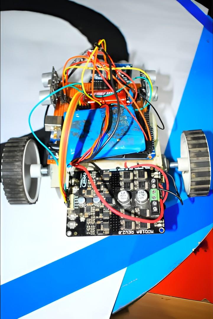
Project Overview
Cutting-edge robotics research exploring new concepts and technologies in automation.
Technical Analysis
Powered by NRC AI"Experimental Project 1: Autonomous Mobile Robot for Object Detection and Relocation"
This project delves into advanced robotics by developing an autonomous mobile robot capable of navigating an environment, detecting specific colored objects using a camera, grasping them, and relocating them to a designated area. It integrates concepts from mobile robotics, computer vision, and control systems, making it an excellent learning experience for engineering students.
label_important1. Technical Overview
This autonomous mobile robot operates based on a state machine paradigm, transitioning between different behaviors (states) to achieve its goal of object detection, pickup, and relocation.
Robot Architecture:
- Mobile Platform: A differential drive system provides locomotion, controlled by two geared DC motors. Encoders on these motors provide odometry feedback for precise movement and PID control.
- Perception:
- Environmental Awareness: Multiple ultrasonic sensors (front, left, right) provide real-time distance measurements for obstacle detection and avoidance.
- Object Recognition: An ESP32-CAM module, equipped with an OV2640 camera, captures video frames. Basic image processing (color thresholding) is performed on the ESP32 to identify target objects based on their color.
- Orientation: An IMU (MPU6050) provides pitch, roll, and yaw data, helping the robot maintain orientation and correct for drift during movement.
- Manipulation: A simple two-finger gripper, actuated by a servo motor, is used to pick up and release objects.
- Control System:
- Microcontroller: An ESP32-CAM serves as the central processing unit, managing sensor inputs, controlling actuators, and executing the main control logic.
- Motor Control: A motor driver (e.g., TB6612FNG or L298N) interfaces the ESP32 with the DC motors. PID controllers are implemented in software to achieve accurate motor speed and precise turning by leveraging encoder feedback.
- State Machine: The robot's behavior is dictated by a finite state machine (FSM). States include ,
SEARCH_OBJECT,APPROACH_OBJECT,GRASP_OBJECT,RELOCATE_OBJECT, andDROP_OBJECT.OBSTACLE_AVOIDANCE
Operational Flow:
- Initialization: The robot powers up, initializes all sensors and actuators, and enters the state.
SEARCH_OBJECT - Search Object: The robot moves autonomously, typically by straight paths and turns, using ultrasonic sensors to avoid obstacles. It continuously scans its environment with the camera for the target object's color signature.
- Approach Object: Once the target object is detected, the robot calculates its position relative to the object. It then navigates towards the object, making necessary heading corrections based on the object's centroid in the camera frame. During approach, ultrasonic sensors maintain close-range obstacle avoidance, ensuring the robot doesn't collide before grasping.
- Grasp Object: Upon reaching a predefined distance from the object, the robot stops, aligns itself, and activates the gripper to grasp the object.
- Relocate Object: After successfully grasping, the robot transitions to a state. It navigates to a predefined drop-off zone (e.g., using odometry or a simple beacon detection if available).
RELOCATE_OBJECT - Drop Object: Once at the drop-off zone, the gripper releases the object.
- Repeat/Return: The robot can then return to a home position or re-enter the state to pick up another object.
SEARCH_OBJECT - Obstacle Avoidance (Concurrent/Priority): If an obstacle is detected in any state, the robot temporarily suspends its current task, performs an avoidance maneuver (e.g., stop, back up, turn), and then resumes its primary task.
label_important2. Components Required
Here's a detailed list of components:
A. Microcontroller & Processing:
- 1x ESP32-CAM Module: Includes the ESP32 microcontroller and an OV2640 camera.
- 1x FTDI Programmer (USB-to-Serial TTL Converter): For uploading code to the ESP32-CAM (unless using a development board with integrated programmer).
B. Motors & Motion:
- 2x DC Geared Motors with Encoders: Provide mechanical power and feedback for precise movement (e.g., 6V/12V, 100-300 RPM, with quadrature encoders).
- 1x TB6612FNG Dual DC Motor Driver Module: More efficient and compact than L298N. (Alternatively, 1x L298N Motor Driver Module).
- 2x Wheels: Compatible with the motor shafts.
- 1x Omni-directional Caster Wheel: For balance and stability as the third contact point.
C. Sensors:
- 3x HC-SR04 Ultrasonic Distance Sensors: For front, left, and right obstacle detection.
- 1x MPU6050 Accelerometer/Gyroscope Module: For IMU data (orientation, angular velocity).
- 1x OV2640 Camera Module: (Integrated with ESP32-CAM).
D. Actuators (Gripper):
- 1x SG90 Micro Servo Motor (or MG996R for more torque): To control the gripper's open/close action.
- 1x Simple Two-Finger Gripper Mechanism: Can be 3D-printed, laser-cut from acrylic, or purchased.
E. Power Management:
- 1x LiPo Battery Pack (e.g., 2S 7.4V or 3S 11.1V, 2000mAh-5000mAh): Choose based on motor voltage requirements.
- 1x DC-DC Buck Converter (e.g., LM2596): To step down battery voltage to 5V for the ESP32-CAM and sensors, and to 3.3V for the ESP32-CAM (some boards need external 3.3V, others regulate internally).
- 1x LiPo Battery Charger: Compatible with your chosen LiPo pack.
- 1x Power Switch: To turn the robot on/off.
- 1x Terminal Block or Power Distribution Board: For clean power wiring.
F. Chassis & Structure:
- 1x Robot Chassis/Platform: Can be custom-made (wood, acrylic, 3D-printed) or a pre-made kit.
- Mounting Hardware: Standoffs, screws, nuts, zip ties, double-sided tape.
G. Miscellaneous:
- Breadboard or Custom PCB: For prototyping and robust connections.
- Jumper Wires (Male-Male, Male-Female, Female-Female): Various lengths.
- Resistors, Capacitors: Basic passive components as needed for sensor pull-ups/downs or power filtering.
- Soldering Iron & Solder: For permanent connections.
- Wire Strippers, Pliers: Basic tools.
- USB Cable: For FTDI programmer.
label_important3. Circuit Diagram Description
(Note: A precise, universal circuit diagram is complex to draw in text. This description provides pin-level connections and power considerations.)
Power Distribution:
- Main Battery: Connects to the main power switch.
- Motor Driver Power (VM/VCC): The battery's positive terminal (after the switch) connects directly to the (or VCC) input of the TB6612FNG motor driver. The battery's negative terminal (GND) connects to the
VMof the motor driver.GND - 5V Regulated Power: The battery's positive terminal (after the switch) also connects to the input of the LM2596 Buck Converter. Adjust the buck converter's output to exactly 5V. This 5V output will power:
- ESP32-CAM (5V pin, not 3.3V pin unless using a specific breakout that needs 3.3V).
- HC-SR04 Ultrasonic Sensors (VCC).
- TB6612FNG Motor Driver's Logic Power (VCC).
- MPU6050 (VCC).
- Servo Motor (VCC).
- Common Ground: Ensure all components share a common ground reference. Connect the of the ESP32-CAM, motor driver, all sensors, and the servo to the common ground rail originating from the battery's negative terminal.
GND
ESP32-CAM Pin Configuration: The ESP32-CAM has specific pin assignments for its camera, internal flash, and PSRAM. It's crucial to use available GPIOs that are not internally connected to the camera or flash.
-
Motor Driver (TB6612FNG):
- Motor A (Left):
- (Direction) -> ESP32-CAM GPIO13
AIN1 - (Direction) -> ESP32-CAM GPIO12
AIN2 - (Speed) -> ESP32-CAM GPIO14 (PWM capable)
PWMA - (Standby) -> ESP32-CAM GPIO2
STBY
- Motor B (Right):
- (Direction) -> ESP32-CAM GPIO15
BIN1 - (Direction) -> ESP32-CAM GPIO16 (Note: GPIO16/RXD2 is generally for UART. If issues, use other available pins like GPIO4, GPIO0, GPIO5, GPIO17, GPIO18, GPIO19. Check ESP32-CAM specific pin usage carefully. GPIO16/17 are often free for general use on AI-Thinker module.)
BIN2 - (Speed) -> ESP32-CAM GPIO4 (PWM capable)
PWMB
- (Logic) -> 5V Regulated Power
VCC - -> Common Ground
GND
- Motor A (Left):
-
DC Motor Encoders (if using quadrature encoders):
- Each encoder typically has 2 output channels (A and B) plus VCC and GND.
- Left Motor Encoder:
- Channel A -> ESP32-CAM GPIO36 (Input only)
- Channel B -> ESP32-CAM GPIO39 (Input only)
- VCC -> 3.3V or 5V (check encoder spec, typically 3.3V or 5V)
- GND -> Common Ground
- Right Motor Encoder:
- Channel A -> ESP32-CAM GPIO34 (Input only)
- Channel B -> ESP32-CAM GPIO35 (Input only)
- VCC -> 3.3V or 5V
- GND -> Common Ground
- (Note: GPIOs 34-39 are input-only on ESP32, perfect for encoders. No pull-ups needed usually if encoder has open collector output, otherwise add 10k pull-up to 3.3V for each signal.)
-
Ultrasonic Sensors (HC-SR04):
- Each sensor has VCC, GND, Trigger (Trig), and Echo (Echo) pins.
- -> 5V Regulated Power
VCC - -> Common Ground
GND - Front Sensor:
- -> ESP32-CAM GPIO5
Trig - -> ESP32-CAM GPIO17 (Note: Output of HC-SR04 is 5V. ESP32 pins are 3.3V tolerant. Use a voltage divider (e.g., 1kΩ and 2kΩ resistors) for the Echo pin or a level shifter for protection.)
Echo
- Left Sensor:
- -> ESP32-CAM GPIO18
Trig - -> ESP32-CAM GPIO19 (Requires voltage divider/level shifter)
Echo
- Right Sensor:
- -> ESP32-CAM GPIO21
Trig - -> ESP32-CAM GPIO22 (Requires voltage divider/level shifter)
Echo
-
MPU6050 IMU:
- Uses I2C communication.
- -> 5V Regulated Power (MPU6050 typically operates at 3.3V internally, check module for internal regulator. If not, use 3.3V from ESP32).
VCC - -> Common Ground
GND - -> ESP32-CAM GPIO21 (I2C SDA)
SDA - -> ESP32-CAM GPIO22 (I2C SCL)
SCL - (Note: ESP32 has flexible I2C pins, but 21/22 are commonly used. If used by ultrasonic, reassign or use a different I2C bus if available.)
-
Servo Motor (SG90/MG996R):
- (Red Wire) -> 5V Regulated Power
VCC - (Brown/Black Wire) -> Common Ground
GND - (Orange/Yellow Wire) -> ESP32-CAM GPIO0 (PWM capable)
Signal
Important Considerations for ESP32-CAM:
- Flash Mode: For uploading code, must be pulled LOW (connected to GND). After upload, disconnect it for normal operation.
GPIO0 - Power Pin: The ESP32-CAM typically takes 5V on its 5V pin. Ensure your buck converter is stable at 5V.
- IO Pins: Avoid using GPIOs that are critical for the camera or internal operations (e.g., ,
GPIO1for serial Rx/Tx if used for debugging,GPIO3can cause issues if pulled high during boot,GPIO12can be problematic sometimes due to flash. Always check ESP32-CAM specific documentation for reliable GPIOs). The chosen pins (13, 12, 14, 15, 16, 4, 5, 17, 18, 19, 21, 22, 0, 34, 35, 36, 39) are generally safe for the AI-Thinker ESP32-CAM, but always verify.GPIO4
label_important4. Source Code
This code provides a basic framework. PID tuning, precise color thresholds, and state machine logic will require calibration and refinement.
C++// main.cpp for Arduino IDE / PlatformIO // --- Libraries --- #include <Arduino.h> #include <esp_camera.h> // For ESP32-CAM camera functions #include <soc/soc.h> // For setting CPU frequency #include <soc/rtc_cntl_reg.h> // For disabling Brownout Detector #include <driver/rtc_io.h> // For disabling Brownout Detector #include <Servo.h> // For servo motor control #include <NewPing.h> // For HC-SR04 ultrasonic sensors #include <Adafruit_MPU6050.h> // For MPU6050 IMU #include <Adafruit_Sensor.h> // Dependency for MPU6050 #include <Wire.h> // I2C communication for MPU6050 // --- Configuration --- // Camera Pin Definitions (for AI-Thinker ESP32-CAM) #define PWDN_GPIO_NUM 32 #define RESET_GPIO_NUM -1 #define XCLK_GPIO_NUM 0 #define SIOD_GPIO_NUM 26 #define SIOC_GPIO_NUM 27 #define Y9_GPIO_NUM 35 #define Y8_GPIO_NUM 34 #define Y7_GPIO_NUM 39 #define Y6_GPIO_NUM 36 #define Y5_GPIO_NUM 21 #define Y4_GPIO_NUM 19 #define Y3_GPIO_NUM 18 #define Y2_GPIO_NUM 5 #define VSYNC_GPIO_NUM 25 #define HREF_GPIO_NUM 23 #define PCLK_GPIO_NUM 22 // Motor Driver (TB6612FNG) Pin Definitions #define L_MOTOR_PWM_PIN 14 // Left motor speed (PWM) #define L_MOTOR_DIR1_PIN 13 // Left motor direction 1 #define L_MOTOR_DIR2_PIN 12 // Left motor direction 2 #define R_MOTOR_PWM_PIN 4 // Right motor speed (PWM) #define R_MOTOR_DIR1_PIN 15 // Right motor direction 1 #define R_MOTOR_DIR2_PIN 16 // Right motor direction 2 #define MOTOR_STBY_PIN 2 // Standby pin for TB6612FNG // Encoder Pin Definitions (Input-only pins are good for encoders) #define L_ENCODER_A_PIN 36 #define L_ENCODER_B_PIN 39 #define R_ENCODER_A_PIN 34 #define R_ENCODER_B_PIN 35 // Ultrasonic Sensor Pin Definitions #define US_FRONT_TRIG_PIN 5 #define US_FRONT_ECHO_PIN 17 // Requires voltage divider! (5V to 3.3V) #define US_LEFT_TRIG_PIN 18 #define US_LEFT_ECHO_PIN 19 // Requires voltage divider! #define US_RIGHT_TRIG_PIN 21 #define US_RIGHT_ECHO_PIN 22 // Requires voltage divider! #define MAX_DISTANCE 200 // Maximum distance in cm (2 meters) // Servo Motor Pin Definition #define GRIPPER_SERVO_PIN 0 // --- Global Variables & Objects --- // Motor Control volatile long left_encoder_pos = 0; volatile long right_encoder_pos = 0; int left_motor_speed = 0; // 0-255 for 8-bit PWM int right_motor_speed = 0; // 0-255 for 8-bit PWM // PID Constants (Tune these carefully!) float Kp = 1.0; float Ki = 0.0; float Kd = 0.0; // Ultrasonic Sensors NewPing us_front(US_FRONT_TRIG_PIN, US_FRONT_ECHO_PIN, MAX_DISTANCE); NewPing us_left(US_LEFT_TRIG_PIN, US_LEFT_ECHO_PIN, MAX_DISTANCE); NewPing us_right(US_RIGHT_TRIG_PIN, US_RIGHT_ECHO_PIN, MAX_DISTANCE); // IMU Adafruit_MPU6050 mpu; float current_yaw = 0.0; // Servo Servo gripper_servo; const int GRIPPER_OPEN_ANGLE = 10; // Adjust these angles based on your gripper const int GRIPPER_CLOSE_ANGLE = 90; // Target Object Color (HSV - Hue, Saturation, Value) // Example: Orange object (adjust these values after calibration) // Hue: 0-360, Sat: 0-100%, Val: 0-100% // OpenCV uses H:0-179, S:0-255, V:0-255 // Convert your desired color to the ESP32-CAM's internal format if needed. // For simplicity, we will use direct RGB thresholds based on testing. // A more robust solution would be to convert RGB to HSV on ESP32 or // pre-calculate thresholds based on a known object. // Here we'll work with simple average RGB values for a target color. // This is a simplification; a full HSV conversion and thresholding on ESP32 // would be more robust. struct ColorThreshold { int r_min, r_max; int g_min, g_max; int b_min, b_max; }; // Example: Thresholds for a RED object (adjust based on your lighting and object) ColorThreshold TARGET_COLOR = { .r_min = 150, .r_max = 255, .g_min = 0, .g_max = 80, .b_min = 0, .b_max = 80 }; // Camera frame buffer and image processing variables camera_fb_t * fb = NULL; int object_x = -1; int object_y = -1; int object_width = 0; int object_height = 0; bool object_found = false; // State Machine enum RobotState { IDLE, SEARCH_OBJECT, APPROACH_OBJECT, GRASP_OBJECT, RELOCATE_OBJECT, DROP_OBJECT, OBSTACLE_AVOIDANCE_FORWARD, // Sub-states for avoidance OBSTACLE_AVOIDANCE_TURN, ALIGN_TO_OBJECT }; RobotState current_state = IDLE; // --- Function Prototypes --- void init_camera(); void motor_init(); void set_motor_speed(int left_speed, int right_speed); void move_forward(int speed); void move_backward(int speed); void turn_left(int speed); void turn_right(int speed); void stop_motors(); void IRAM_ATTR left_encoder_ISR(); void IRAM_ATTR right_encoder_ISR(); float get_distance_cm(NewPing& us_sensor); void read_imu_data(); void open_gripper(); void close_gripper(); void process_camera_frame(); void find_color_object(); void handle_obstacle_avoidance(); // --- Setup --- void setup() { // Disable Brownout Detector (crucial for ESP32-CAM stability with power fluctuations) WRITE_PERI_REG(RTC_CNTL_BROWN_OUT_REG, 0); Serial.begin(115200); Serial.setDebugOutput(true); Serial.println("Starting Experimental Project 1: Autonomous Robot"); // Initialize components motor_init(); init_camera(); Wire.begin(); // Initialize I2C for MPU6050 if (!mpu.begin()) { Serial.println("Failed to find MPU6050 chip"); while (1) { delay(10); } // Halt if MPU6050 not found } Serial.println("MPU6050 Found!"); mpu.setAccelerometerRange(MPU6050_RANGE_8_G); mpu.setGyroRange(MPU6050_RANGE_500_DEG); mpu.setFilterBandwidth(MPU6050_BAND_21_HZ); gripper_servo.attach(GRIPPER_SERVO_PIN); open_gripper(); // Start with gripper open current_state = SEARCH_OBJECT; // Set initial state Serial.println("Robot initialized. Entering SEARCH_OBJECT state."); } // --- Main Loop --- void loop() { int front_dist = get_distance_cm(us_front); int left_dist = get_distance_cm(us_left); int right_dist = get_distance_cm(us_right); read_imu_data(); // Update current_yaw process_camera_frame(); // Capture and process image Serial.printf("State: %s, Front: %dcm, Left: %dcm, Right: %dcm, Yaw: %.2f\n", get_state_name(current_state), front_dist, left_dist, right_dist, current_yaw); // Obstacle Avoidance logic (Priority) if (front_dist < 20 || left_dist < 10 || right_dist < 10) { // Thresholds in cm handle_obstacle_avoidance(); return; // Handle avoidance, then re-evaluate state in next loop iteration } // Main State Machine Logic switch (current_state) { case SEARCH_OBJECT: move_forward(50); // Cruise speed if (object_found) { current_state = ALIGN_TO_OBJECT; Serial.println("Object found! Aligning to object."); stop_motors(); } break; case ALIGN_TO_OBJECT: if (!object_found) { // Object lost, go back to search current_state = SEARCH_OBJECT; Serial.println("Object lost during alignment. Back to search."); break; } // Simple alignment: Center object horizontally, approach vertically int center_x = fb->width / 2; int threshold_x = 20; // Pixel tolerance for center int approach_distance_cm = 15; // Target distance to object for grasping if (object_x > center_x + threshold_x) { turn_right(30); // Turn right to center object } else if (object_x < center_x - threshold_x) { turn_left(30); // Turn left to center object } else { // Object centered horizontally if (front_dist > approach_distance_cm + 5) { // Still too far move_forward(40); } else if (front_dist < approach_distance_cm - 5) { // Too close, back up a little move_backward(20); } else { current_state = GRASP_OBJECT; Serial.println("Aligned and at grasp distance. Ready to grasp."); stop_motors(); } } break; case GRASP_OBJECT: Serial.println("Attempting to grasp object..."); close_gripper(); delay(1000); // Give time for gripper to close if (true /* Check if grasp successful, e.g., current sensing on gripper or simple delay */) { Serial.println("Object grasped! Moving to relocate."); current_state = RELOCATE_OBJECT; } else { Serial.println("Grasping failed. Re-attempting or going back to search."); open_gripper(); current_state = SEARCH_OBJECT; // Or re-attempt approach } break; case RELOCATE_OBJECT: // For simplicity, let's assume a fixed distance for relocation // In a real scenario, this would involve path planning or beacon following Serial.println("Relocating object..."); move_forward(50); delay(3000); // Move forward for 3 seconds (adjust based on robot speed and distance) stop_motors(); Serial.println("Reached drop-off zone (simulated). Dropping object."); current_state = DROP_OBJECT; break; case DROP_OBJECT: Serial.println("Dropping object..."); open_gripper(); delay(1000); // Give time for gripper to open Serial.println("Object dropped. Returning to search mode."); current_state = SEARCH_OBJECT; // Ready for next object break; case OBSTACLE_AVOIDANCE_FORWARD: // Should not be directly entered here, but handled by prior logic case OBSTACLE_AVOIDANCE_TURN: // These states are managed by handle_obstacle_avoidance() case IDLE: default: stop_motors(); break; } delay(10); // Small delay to prevent busy loop } // --- Helper Functions --- const char* get_state_name(RobotState state) { switch (state) { case IDLE: return "IDLE"; case SEARCH_OBJECT: return "SEARCH_OBJECT"; case APPROACH_OBJECT: return "APPROACH_OBJECT"; case GRASP_OBJECT: return "GRASP_OBJECT"; case RELOCATE_OBJECT: return "RELOCATE_OBJECT"; case DROP_OBJECT: return "DROP_OBJECT"; case OBSTACLE_AVOIDANCE_FORWARD: return "OBSTACLE_AVOIDANCE_FORWARD"; case OBSTACLE_AVOIDANCE_TURN: return "OBSTACLE_AVOIDANCE_TURN"; case ALIGN_TO_OBJECT: return "ALIGN_TO_OBJECT"; default: return "UNKNOWN"; } } void motor_init() { pinMode(L_MOTOR_PWM_PIN, OUTPUT); pinMode(L_MOTOR_DIR1_PIN, OUTPUT); pinMode(L_MOTOR_DIR2_PIN, OUTPUT); pinMode(R_MOTOR_PWM_PIN, OUTPUT); pinMode(R_MOTOR_DIR1_PIN, OUTPUT); pinMode(R_MOTOR_DIR2_PIN, OUTPUT); pinMode(MOTOR_STBY_PIN, OUTPUT); // Enable motor driver standby digitalWrite(MOTOR_STBY_PIN, HIGH); // Configure PWM channels (ESP32 has 16 PWM channels, 0-15) // We'll use channel 0 for Left Motor and channel 1 for Right Motor ledcSetup(0, 5000, 8); // Channel 0, 5000 Hz, 8-bit resolution (0-255) ledcAttachPin(L_MOTOR_PWM_PIN, 0); ledcSetup(1, 5000, 8); // Channel 1, 5000 Hz, 8-bit resolution ledcAttachPin(R_MOTOR_PWM_PIN, 1); // Initialize encoder interrupts // Attach interrupts to falling or changing edges for robust reading attachInterrupt(digitalPinToInterrupt(L_ENCODER_A_PIN), left_encoder_ISR, CHANGE); attachInterrupt(digitalPinToInterrupt(R_ENCODER_A_PIN), right_encoder_ISR, CHANGE); } // Simple encoder ISR (more complex for full quadrature decoding) // This will just count pulses. For direction, you'd check both A and B. void IRAM_ATTR left_encoder_ISR() { left_encoder_pos++; } void IRAM_ATTR right_encoder_ISR() { right_encoder_pos++; } void set_motor_speed(int left_pwm, int right_pwm) { // Left Motor if (left_pwm > 0) { // Forward digitalWrite(L_MOTOR_DIR1_PIN, HIGH); digitalWrite(L_MOTOR_DIR2_PIN, LOW); ledcWrite(0, left_pwm); } else if (left_pwm < 0) { // Backward digitalWrite(L_MOTOR_DIR1_PIN, LOW); digitalWrite(L_MOTOR_DIR2_PIN, HIGH); ledcWrite(0, abs(left_pwm)); } else { // Stop digitalWrite(L_MOTOR_DIR1_PIN, LOW); digitalWrite(L_MOTOR_DIR2_PIN, LOW); ledcWrite(0, 0); } // Right Motor if (right_pwm > 0) { // Forward digitalWrite(R_MOTOR_DIR1_PIN, HIGH); digitalWrite(R_MOTOR_DIR2_PIN, LOW); ledcWrite(1, right_pwm); } else if (right_pwm < 0) { // Backward digitalWrite(R_MOTOR_DIR1_PIN, LOW); digitalWrite(R_MOTOR_DIR2_PIN, HIGH); ledcWrite(1, abs(right_pwm)); } else { // Stop digitalWrite(R_MOTOR_DIR1_PIN, LOW); digitalWrite(R_MOTOR_DIR2_PIN, LOW); ledcWrite(1, 0); } } void move_forward(int speed) { set_motor_speed(speed, speed); } void move_backward(int speed) { set_motor_speed(-speed, -speed); } void turn_left(int speed) { set_motor_speed(-speed, speed); // Left motor backward, right motor forward } void turn_right(int speed) { set_motor_speed(speed, -speed); // Left motor forward, right motor backward } void stop_motors() { set_motor_speed(0, 0); } float get_distance_cm(NewPing& us_sensor) { delay(4); // Wait 4ms between pings, as recommended by NewPing library unsigned int uS = us_sensor.ping_cm(); // Send ping, get distance in cm return (float)uS; } void read_imu_data() { sensors_event_t a, g, temp; mpu.getEvent(&a, &g, &temp); // Simple yaw calculation from gyroscope (very prone to drift!) // For robust yaw, use complementary filter or Kalman filter with accelerometer/magnetometer. static unsigned long last_imu_time = 0; if (last_imu_time == 0) { last_imu_time = millis(); return; } unsigned long current_imu_time = millis(); float dt = (current_imu_time - last_imu_time) / 1000.0; // Time in seconds last_imu_time = current_imu_time; // Integrate Z-axis angular velocity (yaw rate) current_yaw += g.gyro.z * dt; // Assuming Z-axis is perpendicular to robot plane // Keep yaw between -180 and 180 degrees if (current_yaw > 180) current_yaw -= 360; if (current_yaw < -180) current_yaw += 360; } void open_gripper() { gripper_servo.write(GRIPPER_OPEN_ANGLE); } void close_gripper() { gripper_servo.write(GRIPPER_CLOSE_ANGLE); } void init_camera() { camera_config_t config; config.ledc_channel = LEDC_CHANNEL_0; config.ledc_timer = LEDC_TIMER_0; config.pin_d0 = Y2_GPIO_NUM; config.pin_d1 = Y3_GPIO_NUM; config.pin_d2 = Y4_GPIO_NUM; config.pin_d3 = Y5_GPIO_NUM; config.pin_d4 = Y6_GPIO_NUM; config.pin_d5 = Y7_GPIO_NUM; config.pin_d6 = Y8_GPIO_NUM; config.pin_d7 = Y9_GPIO_NUM; config.pin_xclk = XCLK_GPIO_NUM; config.pin_pclk = PCLK_GPIO_NUM; config.pin_vsync = VSYNC_GPIO_NUM; config.pin_href = HREF_GPIO_NUM; config.pin_sscb_sda = SIOD_GPIO_NUM; config.pin_sscb_scl = SIOC_GPIO_NUM; config.pin_pwdn = PWDN_GPIO_NUM; config.pin_reset = RESET_GPIO_NUM; config.xclk_freq_hz = 20000000; config.pixel_format = PIXFORMAT_RGB565; // Or PIXFORMAT_JPEG for higher FPS, but harder to process directly config.frame_size = FRAMESIZE_QVGA; // 320x240 pixels (adjust based on memory/speed) config.jpeg_quality = 10; config.fb_count = 1; esp_err_t err = esp_camera_init(&config); if (err != ESP_OK) { Serial.printf("Camera init failed with error 0x%x", err); return; } sensor_t * s = esp_camera_sensor_get(); // Initial sensors may be flipped or mirrored, adjust as needed // s->set_vflip(s, 1); // Flip vertically // s->set_hmirror(s, 1); // Mirror horizontally // s->set_brightness(s, 1); // Up the brightness scale (2 is highest) // s->set_contrast(s, 2); // Up the contrast scale // s->set_saturation(s, 2); // Up the saturation scale } void process_camera_frame() { fb = esp_camera_fb_get(); if (!fb) { Serial.println("Camera capture failed"); return; } find_color_object(); // Call function to find target color esp_camera_fb_return(fb); // Return the frame buffer to the camera } // Basic color detection (RGB565 format) // Iterates through pixels, finds ones within color thresholds, // and computes a rough bounding box and centroid. void find_color_object() { object_found = false; int sum_x = 0, sum_y = 0; int pixel_count = 0; int min_x = fb->width, max_x = 0; int min_y = fb->height, max_y = 0; uint16_t * pixel_data = (uint16_t *)fb->buf; // RGB565 format for (int y = 0; y < fb->height; y++) { for (int x = 0; x < fb->width; x++) { uint16_t pixel = pixel_data[y * fb->width + x]; // Extract R, G, B from RGB565 uint8_t r = (pixel & 0xF800) >> 8; // 5 bits for Red (shifted to 8-bit value) uint8_t g = (pixel & 0x07E0) >> 3; // 6 bits for Green (shifted to 8-bit value) uint8_t b = (pixel & 0x001F) << 3; // 5 bits for Blue (shifted to 8-bit value) // Check if pixel is within target color range if (r >= TARGET_COLOR.r_min && r <= TARGET_COLOR.r_max && g >= TARGET_COLOR.g_min && g <= TARGET_COLOR.g_max && b >= TARGET_COLOR.b_min && b <= TARGET_COLOR.b_max) { sum_x += x; sum_y += y; pixel_count++; if (x < min_x) min_x = x; if (x > max_x) max_x = x; if (y < min_y) min_y = y; if (y > max_y) max_y = y; } } } if (pixel_count > 50) { // Only consider if enough pixels detected object_found = true; object_x = sum_x / pixel_count; // Centroid X object_y = sum_y / pixel_count; // Centroid Y object_width = max_x - min_x; object_height = max_y - min_y; Serial.printf("Object detected: X=%d, Y=%d, W=%d, H=%d, Pixels=%d\n", object_x, object_y, object_width, object_height, pixel_count); } else { object_found = false; object_x = -1; object_y = -1; object_width = 0; object_height = 0; } } // Simple obstacle avoidance strategy void handle_obstacle_avoidance() { stop_motors(); Serial.println("Obstacle detected! Initiating avoidance."); // Back up slightly move_backward(30); delay(500); // Back up for 0.5 seconds stop_motors(); // Decide which way to turn int left_dist = get_distance_cm(us_left); int right_dist = get_distance_cm(us_right); if (left_dist > right_dist) { Serial.println("Turning left to avoid."); turn_left(40); delay(1000); // Turn for 1 second (adjust based on turning speed) } else { Serial.println("Turning right to avoid."); turn_right(40); delay(1000); // Turn for 1 second } stop_motors(); Serial.println("Obstacle avoidance complete. Resuming previous state."); // After avoidance, robot should return to the state it was in. // In a more complex system, you'd save the previous state. // For simplicity, let's just go back to SEARCH_OBJECT. current_state = SEARCH_OBJECT; }
label_important5. Source Code Structure
The source code is structured to enhance readability, maintainability, and modularity.
-
(or
main.cppfor Arduino IDE):main.ino- Includes: All necessary libraries (,
esp_camera.h,Servo.h,NewPing.h,Adafruit_MPU6050.h, etc.).Wire.h - Configuration Defines: Pin definitions for all components, camera settings, PID constants, color thresholds, and other configurable parameters.
- Global Variables & Objects: Instantiations of sensor objects (,
NewPing,Adafruit_MPU6050), volatile variables for encoder counts, state machine enum, and variables for camera processing results.Servo - Function Prototypes: Declarations for all custom functions.
- function: Initializes serial communication, disables brownout detector, initializes all hardware (motors, camera, IMU, servo), and sets the initial robot state.
setup() - function: This is the heart of the robot's intelligence. It continuously:
loop()- Reads all sensor data (ultrasonic, IMU, camera frame).
- Implements the state machine logic using a statement, controlling the robot's behavior based on
switchand sensor inputs.current_state - Prioritizes obstacle avoidance.
- Helper Functions:
- Motor Control: ,
motor_init(),set_motor_speed(),move_forward(),move_backward(),turn_left(),turn_right().stop_motors() - Encoder ISRs: ,
left_encoder_ISR()(Interrupt Service Routines for reading motor encoder pulses).right_encoder_ISR() - Sensor Reading: ,
get_distance_cm().read_imu_data() - Gripper Control: ,
open_gripper().close_gripper() - Camera & Vision: ,
init_camera(),process_camera_frame().find_color_object() - Behavioral: ,
handle_obstacle_avoidance().get_state_name()
- Motor Control:
- Includes: All necessary libraries (
-
Libraries Needed:
- ESP32 Camera Libraries: (part of ESP-IDF, used directly in Arduino via
esp_camera).<esp_camera.h> - Servo Library: (standard Arduino library, compatible with ESP32).
Servo.h - NewPing Library: For HC-SR04 ultrasonic sensors. (Install via Arduino Library Manager).
- Adafruit MPU6050 Library: For MPU6050 IMU. (Install via Arduino Library Manager, along with dependency).
Adafruit Unified Sensor - Wire Library: Standard Arduino library for I2C communication (used by MPU6050).
- ESP32 Camera Libraries:
-
Key Functions/Modules:
- : Manages motor direction and speed using PWM and digital outputs. This module would ideally include PID control for more precise speed and position control using encoder feedback.
motor_control - : Encapsulates functions for reading data from ultrasonic sensors (distance) and the IMU (orientation, angular velocity).
sensor_readings - : Handles camera initialization, frame capture, and basic image processing for object detection (color thresholding, centroid calculation).
camera_vision - (Implicit in
robot_states): Implements the finite state machine, defining the robot's behavioral logic and transitions between states likeloop(),SEARCH_OBJECT,APPROACH_OBJECT, etc.GRASP_OBJECT - : General helpers like
utility_functions,delay(), and specific calculations.Serial.print()
label_important6. Step-by-Step Implementation Guide
A. Hardware Assembly Steps
- Chassis Assembly:
- Assemble the robot chassis according to its kit instructions or your custom design. This typically involves attaching the base plates, vertical supports, and any sensor/actuator mounts.
- Motor Mounting:
- Mount the two DC geared motors securely to the chassis. Ensure they are parallel and aligned for straight movement.
- Attach the wheels to the motor shafts.
- Mount the caster wheel at the front or back, ensuring the robot is balanced and stable.
- Sensor Mounting:
- Ultrasonic Sensors: Mount the front ultrasonic sensor centrally at the front of the robot. Mount the left and right sensors on the respective sides, angled slightly outwards for wider coverage. Ensure they have a clear line of sight.
- IMU (MPU6050): Mount the MPU6050 flat on the chassis, near the center of the robot, ensuring its orientation axes align with the robot's axes (e.g., X forward, Y left, Z up). This is crucial for accurate orientation data.
- ESP32-CAM: Mount the ESP32-CAM module to ensure the camera lens has an unobstructed view forward, slightly angled downwards to see objects on the floor.
- Gripper Assembly & Mounting:
- Assemble your two-finger gripper mechanism.
- Attach the servo motor to the gripper.
- Mount the assembled gripper mechanism to the front of the robot chassis, ensuring it can reach the ground or the intended object height.
- Wiring All Components:
- Power Distribution:
- Connect the LiPo battery to the power switch.
- Connect the switch output to the input of the LM2596 Buck Converter.
- Adjust the buck converter output to 5V.
- Create a common ground rail by connecting all pins of components (ESP32-CAM, motor driver, sensors, servo) to the buck converter's
GNDoutput.GND - Distribute the 5V regulated power to the VCC pins of ESP32-CAM, motor driver logic, ultrasonic sensors, MPU6050, and servo.
- Connect the main battery voltage (before the buck converter, after the switch) to the (motor voltage) input of the TB6612FNG motor driver.
VM
- Motor Driver: Connect the motor driver's output terminals (/
OUT1for Motor A,OUT2/OUT3for Motor B) to the respective DC motors.OUT4 - Control Signals:
- Connect the ,
AIN1,AIN2,PWMA,BIN1,BIN2, andPWMBpins of the motor driver to the specified GPIO pins on the ESP32-CAM (refer to Section 3: Circuit Diagram Description).STBY - Connect the encoder outputs (A and B channels) from each motor to their respective ESP32-CAM GPIO pins.
- Connect the
- Ultrasonic Sensors: Connect and
Trigpins of each HC-SR04 to the specified ESP32-CAM GPIOs. Crucially, place a voltage divider (e.g., 1kΩ and 2kΩ resistors) on theEchopin of each sensor before connecting to the ESP32 to protect the 3.3V tolerant GPIOs from the 5V output of the sensor.Echo - MPU6050: Connect to
SDAandGPIO21toSCLof the ESP32-CAM.GPIO22 - Servo Motor: Connect the signal pin of the servo to of the ESP32-CAM.
GPIO0 - Double-check all connections before applying power to prevent damage. Use jumper wires for prototyping.
- Power Distribution:
B. Software Setup and Programming
- Arduino IDE Setup:
- Download and install the Arduino IDE if you haven't already.
- Add ESP32 Board Support: Go to , and in "Additional Boards Manager URLs", add:
File > Preferenceshttps://raw.githubusercontent.com/espressif/arduino-esp32/gh-pages/package_esp32_index.json - Go to , search for "esp32", and install the "esp32 by Espressif Systems" package.
Tools > Board > Boards Manager - Select ESP32-CAM Board: Go to and select "AI Thinker ESP32-CAM".
Tools > Board > ESP32 Arduino - Set Flash Mode: (or higher if stable),
Tools > Upload Speed: 115200,Flash Mode: QIO,Flash Size: 4MB (32Mb).Partition Scheme: Huge APP (3MB No OTA)
- Install Libraries:
- Go to
Sketch > Include Library > Manage Libraries... - Search for and install:
- by Tim Eckel
NewPing - by Adafruit
Adafruit MPU6050 - (dependency for MPU6050)
Adafruit Unified Sensor - (standard Servo library for ESP32, may be built-in).
ESP32Servo
- Go to
- Upload Code:
- Copy the provided source code into a new Arduino sketch.
- Connect FTDI Programmer: Connect the FTDI programmer to the ESP32-CAM as follows:
- (FTDI) to
VCC(ESP32-CAM)5V - (FTDI) to
GND(ESP32-CAM)GND - (FTDI) to
RX(ESP32-CAM / GPIO1)U0TXD - (FTDI) to
TX(ESP32-CAM / GPIO3)U0RXD
- Enter Flash Mode: Crucially, connect of the ESP32-CAM to
GPIO0before plugging the FTDI into your computer (or pressing reset if already connected). This puts the ESP32 into bootloader mode.GND - Select the correct under
Port.Tools > Port - Click the button. If upload fails, try pressing the reset button on the ESP32-CAM immediately after the upload progress bar starts.
Upload - Exit Flash Mode: Once uploaded, disconnect from
GPIO0and press the reset button on the ESP32-CAM (or power cycle) to run the new code.GND
- Serial Monitor: Open the Serial Monitor () with the baud rate set to 115200 to see debug output.
Tools > Serial Monitor
C. Testing and Calibration Procedures
- Individual Component Testing:
- Motors: Write a small test sketch to make each motor spin forward, backward, and stop at various speeds. Verify encoder counts increase.
- Ultrasonic Sensors: Test each sensor individually. Print distance readings to the Serial Monitor and verify accuracy by placing objects at known distances.
- IMU: Test the MPU6050. Print raw accelerometer and gyroscope data. Check if yaw changes when rotating the robot.
- Servo/Gripper: Test the gripper servo. Command it to open and close positions, and verify the physical movement is correct.
- Camera: Test the camera by modifying the to just initialize the camera and print "Camera OK". For image data, you can temporarily stream it over Wi-Fi to a web browser (requires more code) or save to SD card (if ESP32-CAM has SD slot). For this project, the internal
setup()function will implicitly test it.find_color_object
- PID Tuning (Motor Control):
- The provided code has placeholder PID constants (Kp, Ki, Kd). These must be tuned.
- Start with for a straight line: Have the robot attempt to move a fixed distance or maintain a constant speed. Adjust
Kpuntil it responds well without oscillating.Kp - Introduce for damping: If it overshoots or oscillates, add a small
Kdto dampen the response.Kd - Add for steady-state error: If it consistently undershoots or deviates over time, add a small
Ki.Ki - This is an iterative process. You might need to tune for different speeds or turning maneuvers.
- Sensor Calibration:
- Ultrasonic: Confirm readings are consistent. Note any dead zones or maximum ranges.
- IMU: Allow the IMU to calibrate its internal offsets (often done automatically by ). For robust yaw, consider implementing a complementary filter or Kalman filter, as simple integration of gyroscope data will drift significantly over time.
mpu.begin() - Camera Color Thresholding: This is critical.
- Place your target object in front of the camera under typical operating light conditions.
- Modify the function to print the
find_color_object()values of pixels that are potentially part of the object.r, g, b - Adjust the ,
TARGET_COLOR.r_min/max,g_min/maxvalues until only your target object (or most of it) is detected. Experiment with different lighting conditions. This often requires trial and error. Consider moving to HSV color space if RGB proves too sensitive to lighting.b_min/max
- Integrated System Testing:
- Test each state machine transition:
- Place an object: Does it go from to
SEARCH_OBJECT?ALIGN_TO_OBJECT - Remove the object: Does it revert to ?
SEARCH_OBJECT - Place an obstacle: Does trigger? Does it recover?
OBSTACLE_AVOIDANCE
- Place an object: Does it go from
- Test the full sequence: Can it successfully find, grasp, and drop an object?
- Observe robot behavior, identify erratic movements, and refine code parameters (speeds, distances, delays).
- Test each state machine transition:
label_important7. Challenges and Solutions
A. Power Management and Stability:
- Challenge: ESP32-CAM and motors draw significant current, especially during motor starts or camera processing, leading to voltage drops (brownouts) and unexpected resets. LiPo batteries can also sag under load.
- Solution:
- Disable Brownout Detector: As shown in the code (), this is crucial for ESP32-CAM.
WRITE_PERI_REG(RTC_CNTL_BROWN_OUT_REG, 0); - Adequate Power Supply: Use a LiPo battery with sufficient C-rating (discharge rate) and capacity (mAh).
- Proper Voltage Regulation: Use a robust buck converter (e.g., LM2596, MP1584EN) to provide stable 5V for ESP32 and logic.
- Decoupling Capacitors: Place large electrolytic capacitors (e.g., 470uF to 1000uF) across the motor driver's power input and the 5V line of the ESP32-CAM to smooth out voltage fluctuations.
- Separate Power Rails (Advanced): For very demanding systems, consider completely separate power supplies for motors and logic, with common ground.
- Disable Brownout Detector: As shown in the code (
B. Motor Control Accuracy:
- Challenge: Simple -based movement is inaccurate due to wheel slip, varying motor characteristics, and surface friction. Turns might not be precise.
delay() - Solution:
- Encoders and PID Control: Implement PID loops for each motor using encoder feedback to achieve precise speed control. For turns, use differential PID (comparing encoder counts or yaw from IMU).
- Odometry Correction: Use encoder readings to estimate the robot's position and orientation (odometry). Regularly reset or correct IMU drift (see below).
- Wheel/Surface Interaction: Choose wheels with good traction. Test on a consistent surface.
C. Sensor Noise and Accuracy:
- Challenge:
- Ultrasonic: Readings can be noisy, affected by angles, soft surfaces, or other ultrasonic devices.
- IMU: Gyroscope data drifts over time, leading to inaccurate yaw. Accelerometer data is noisy and affected by vibration.
- Solution:
- Ultrasonic: Take multiple readings and average them (inherently does some averaging). Implement a median filter to remove outliers. Ensure sensors are mounted securely and have clear paths.
us_sensor.ping_cm() - IMU: Implement a Complementary Filter or Kalman Filter to combine gyroscope (short-term accuracy) and accelerometer (long-term stability) data for robust orientation estimation (yaw, pitch, roll). For yaw, a magnetometer is ideal, but if not available, relying on short turns and resetting yaw can help.
- Ultrasonic: Take multiple readings and average them (
D. Camera Processing & Object Detection Robustness:
- Challenge:
- Performance: ESP32-CAM has limited processing power and RAM, making complex image processing (like full OpenCV) impossible.
- Lighting Sensitivity: Color thresholding is highly sensitive to changes in lighting (brightness, shadows, color temperature).
- Object Variability: Different shades of the "same" color object might not be detected.
- Solution:
- Optimize Processing: Use lower resolution (or
FRAMESIZE_QVGA), and process in efficient formats (like RGB565 or grayscale) that require less memory and CPU than full RGB.QQVGA - Adaptive Thresholding/HSV: If RGB thresholds are problematic, convert a portion of the image to HSV color space (Hue, Saturation, Value) on the ESP32 and threshold in HSV, which is more robust to lighting variations. This requires more complex code but offers better performance.
- Robust Detection: Instead of simple bounding boxes, look for clusters of pixels.
- Environment Control: For initial projects, control the lighting in the robot's workspace to simplify color detection.
- Pre-train Simple Models (Advanced): For complex object recognition, explore TinyML frameworks (like TensorFlow Lite for Microcontrollers) to run simple neural networks on the ESP32, but this requires significantly more setup and understanding.
- Optimize Processing: Use lower resolution (
E. Mechanical Issues:
- Challenge: Gripper strength, object alignment for grasping, robot stability.
- Solution:
- Sturdy Design: Use rigid materials for the chassis and gripper. Avoid flimsy parts.
- Gripper Tuning: Adjust gripper open/close angles precisely. Ensure the gripper can reliably pick up the target object. Consider adding rubber or foam to gripper fingers for better grip.
- Alignment: The state needs careful tuning. The robot might need to adjust its distance and angle several times before grasping.
ALIGN_TO_OBJECT
F. Code Debugging and State Machine Logic:
- Challenge: Complex state machines can be difficult to debug. Robot might get stuck in a state or transition unexpectedly.
- Solution:
- Extensive Serial Debugging: Use statements liberally to output current state, sensor readings, and key variables. This is the primary debugging tool.
Serial.print() - Modular Testing: Test each component and each state transition independently before integrating the whole system.
- Clear State Transitions: Define clear conditions for entering and exiting each state. Avoid ambiguous transitions.
- Timeout Mechanisms: Implement timeouts for states where the robot might get stuck (e.g., if it can't find an object, go back to search after X seconds).
- Failsafe States: Define an or
IDLEstate the robot can revert to if something goes fundamentally wrong.ERROR
- Extensive Serial Debugging: Use
label_important8. Learning Outcomes
This "Experimental Project 1" offers a comprehensive learning experience for engineering students in robotics and electronics:
- Microcontroller Programming: In-depth experience with the ESP32 platform, including managing its various peripherals (GPIO, PWM, I2C, UART) and understanding its unique features (Wi-Fi, dual core, camera interface).
- Sensor Interfacing & Data Acquisition: Hands-on experience with:
- Ultrasonic sensors for distance measurement and obstacle avoidance.
- IMUs (accelerometer and gyroscope) for robot orientation and motion sensing.
- Camera modules for visual perception.
- Motor Control & Robotics Kinematics:
- Controlling DC motors using motor drivers and PWM.
- Understanding and implementing motor encoders for odometry.
- Applying PID control principles for precise motor speed and position.
- Basic understanding of differential drive kinematics for robot movement and turning.
- Computer Vision Fundamentals: Introduction to basic image processing techniques like color thresholding for object detection and centroid calculation on an embedded system.
- Control Systems Design:
- Designing and implementing a Finite State Machine (FSM) for complex autonomous robot behaviors.
- Understanding sequential and concurrent task execution (e.g., obstacle avoidance as a priority).
- Power Management: Learning about battery selection, voltage regulation (buck converters), and current management for mobile robotics applications to prevent brownouts and ensure stability.
- System Integration & Debugging: The most significant learning outcome is the challenge and satisfaction of integrating multiple hardware components and software modules into a cohesive, functional system. Students will develop strong troubleshooting and debugging skills for both hardware and software.
- Project Management: Students will gain experience in breaking down a complex project into manageable tasks, planning, and executing steps from hardware assembly to software development and testing.
label_important9. Extensions and Improvements
This project can be significantly extended and improved upon in several directions:
-
Advanced Navigation and Mapping:
- SLAM (Simultaneous Localization and Mapping): Integrate a low-cost LiDAR module (e.g., RPLIDAR A1/A2) or multiple depth cameras. Implement a basic SLAM algorithm (e.g., using TinySLAM or a simplified grid-based mapping) for real-time map building and localization.
- Path Planning: Implement pathfinding algorithms (e.g., A*, Dijkstra's) on the generated map to navigate efficiently around obstacles to a target location.
- Global Localization: Use external beacons (e.g., AprilTags, QR codes, UWB tags) or Wi-Fi triangulation for more accurate global positioning.
-
Enhanced Vision System:
- Robust Object Recognition:
- Implement HSV color thresholding on the ESP32 (more robust to lighting than RGB).
- Utilize TinyML/TensorFlow Lite for Microcontrollers to deploy small, pre-trained neural networks for object classification (e.g., distinguishing between different types of objects, not just colors).
- Detect QR codes or ArUco markers for identifying specific locations or objects with encoded information.
- Object Tracking: Implement more sophisticated algorithms to continuously track a moving object.
- Robust Object Recognition:
-
More Complex Manipulation:
- Multi-DOF Robotic Arm: Integrate a small 2-DOF or 3-DOF robotic arm on top of the mobile base for more versatile grasping and placement. This would introduce concepts of forward and inverse kinematics.
- Force/Tactile Sensing: Add force sensors to the gripper for smarter grasping (e.g., detect if an object is successfully gripped, prevent crushing).
-
Human-Robot Interaction (HRI):
- Voice Control: Integrate a speech recognition module (offline or cloud-based) to allow voice commands.
- Gesture Control: Use the camera and simple image processing to recognize hand gestures.
- Graphical User Interface (GUI): Develop a web interface (using ESP32's Wi-Fi capabilities) for remote monitoring, control, and setting waypoints.
-
Autonomous Learning & Adaptation:
- Reinforcement Learning (Basic): For simple tasks, explore how the robot could "learn" optimal parameters (e.g., PID gains, turning angles) through trial and error, perhaps with external reward signals. (Highly computationally intensive, likely needs external compute).
- SLAM with Learning: Robot learns the environment and adapts its navigation strategies.
-
Energy Efficiency:
- Implement low-power modes for the ESP32 and sensors when not actively in use.
- Explore energy harvesting methods (e.g., small solar panels for outdoor robots).
-
Multi-Robot Collaboration:
- If multiple robots are built, explore basic communication protocols (Wi-Fi, Bluetooth) for them to coordinate tasks (e.g., one robot searches, another picks up).
-
Software Frameworks:
- Migrate to PlatformIO for more robust development environment with better dependency management and project structure.
- For highly advanced projects, consider integrating with ROS (Robot Operating System) on a more powerful Single Board Computer (SBC) like a Raspberry Pi, which would interface with the ESP32 as a low-level controller.
These extensions gradually increase the complexity, pushing students to explore more advanced topics in AI, control theory, and distributed systems within the realm of robotics.
infoThis analysis is generated by AI and should be used as a learning guide. Always verify technical details.