


Experimental Project 2
Experimental Project 2 is an autonomous engineering project developed by the NIST Robotics Club (NRC) at NIST University, Berhampur. Advanced prototype demonstrating innovative approaches to solving complex robotics challenges.

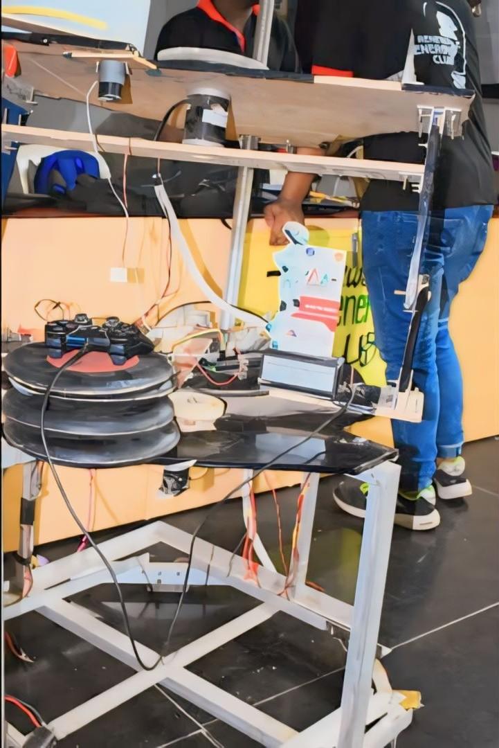
Project Overview
Advanced prototype demonstrating innovative approaches to solving complex robotics challenges.
Technical Analysis
Powered by NRC AIAs a robotics and electronics expert, I'm excited to outline "Experimental Project 2," an advanced prototype designed to demonstrate innovative approaches to solving complex robotics challenges. This project involves a mobile manipulator robot capable of autonomous navigation, object detection and manipulation. It integrates computer vision, mobile robotics, and robotic arm control into a cohesive system, pushing students to tackle real-world robotics complexities.
articleProject: Experimental Project 2 - Autonomous Mobile Manipulator
Project Description: An advanced prototype demonstrating innovative approaches to solving complex robotics challenges. This project involves a mobile manipulator robot that autonomously navigates a predefined area, identifies specific colored objects using a camera, picks them up with a robotic arm, and places them in designated target locations.
label_important1. Technical Overview
"Experimental Project 2" is a sophisticated robotic system composed of two primary sub-systems: a mobile base and a multi-degree-of-freedom (DoF) robotic arm, both coordinated by a distributed control architecture.
Core Functionality:
- Autonomous Navigation: The mobile base navigates its environment, avoiding obstacles and reaching target waypoints. Odometry is used for localization, potentially augmented by an Inertial Measurement Unit (IMU) for drift correction.
- Object Perception: A camera system processes video feeds to detect and identify specific colored objects (e.g., red, green, blue blocks). It determines their 2D image coordinates and, with some calibration, estimates their 3D position relative to the robot.
- Precision Manipulation: Upon identifying a target object, the robotic arm is commanded to move to the object's estimated position, grasp it with a gripper, and then transport it to a designated drop-off zone. Inverse kinematics is crucial for calculating the required joint angles to reach a target XYZ position.
- Integrated Control: A dual-microcontroller setup (Raspberry Pi and ESP32) is employed. The Raspberry Pi handles high-level tasks like computer vision, path planning, and inverse kinematics, while the ESP32 manages low-level real-time control of motors, servos, and sensors. Communication between these two boards is essential for coordinated operation.
Technical Breakdown:
- Mobile Base:
- Locomotion: Differential drive system with two DC geared motors and encoders for precise speed and position control.
- Navigation: Basic path planning (e.g., A* on a simplified grid map) and obstacle avoidance using ultrasonic sensors.
- Control: PID controllers are used for accurate motor speed and position control, ensuring the robot follows planned trajectories.
- Robotic Arm:
- Structure: A 4-DoF (or 5-DoF including gripper rotation) arm constructed from high-torque hobby servos.
- Kinematics: Forward kinematics calculates the end-effector position from joint angles, while inverse kinematics calculates joint angles required to reach a desired end-effector position and orientation.
- Gripper: A simple servo-actuated gripper for picking and placing objects.
- Vision System (Raspberry Pi):
- Hardware: USB Camera connected to the Raspberry Pi.
- Software: OpenCV library for image processing. Techniques include color thresholding (HSV range), contour detection, and centroid calculation to locate objects. Basic perspective transformation can estimate real-world coordinates from pixel data.
- Control Architecture:
- Raspberry Pi (High-Level Controller): Runs Python. Responsible for:
- Image acquisition and processing (OpenCV).
- Object detection and 3D pose estimation.
- Path planning for the mobile base.
- Inverse Kinematics calculations for the arm.
- Decision-making and task sequencing (e.g., "navigate to object," "pick up," "navigate to drop-off").
- Serial communication (UART) with the ESP32 to send movement and arm commands.
- ESP32 (Low-Level Controller): Runs Arduino C++. Responsible for:
- Real-time motor control (PID loops, encoder feedback).
- Servo control for the robotic arm.
- Reading data from ultrasonic sensors (obstacle detection).
- Reading data from IMU (odometry correction, arm stability).
- Serial communication (UART) with the Raspberry Pi to receive commands and send status.
- Implementing a state machine to manage the robot's current operation (e.g., ,
MOVING_BASE,PICKING_UP).PLACING_OBJECT
- Raspberry Pi (High-Level Controller): Runs Python. Responsible for:
This distributed approach leverages the Raspberry Pi's computational power for complex tasks and the ESP32's real-time capabilities for precise hardware control, demonstrating a common paradigm in advanced robotics systems.
label_important2. Components Required
Below is a comprehensive list of components, categorized for clarity.
A. Microcontrollers & Computers:
- 1x Raspberry Pi 4 Model B (4GB/8GB RAM recommended): High-level processing, vision, path planning.
- 1x ESP32 Dev Board (e.g., ESP32-WROOM-32D): Low-level motor/servo control, sensor interfacing.
B. Mechanical Components & Structure:
- 1x Robot Chassis: Differential drive compatible (e.g., acrylic or aluminum platform).
- 2x DC Geared Motors: With high torque (e.g., N20 or JGA25-370 with 6V/12V operation).
- 2x Quadrature Encoders: To be attached to the DC motors for odometry. (Often integrated with motors).
- 2x Robot Wheels: Compatible with motor shafts.
- 1x Omni-directional Wheel / Caster Wheel: For stability and turning.
- 1x 4-DoF Robotic Arm Kit: (e.g., DIY 4-axis acrylic arm or 3D printed parts). Ensure it's compatible with standard hobby servos.
- 1x Servo Gripper: Designed to attach to the robotic arm's end effector.
C. Actuators:
- 2x TB6612FNG Dual DC Motor Driver Module: For controlling the two DC geared motors. (Can handle two motors per module).
- 4-5x High-Torque Standard Servos (e.g., MG996R, DS3218): For the robotic arm joints.
- 1x Standard Servo (e.g., SG90, MG90S): For the gripper actuation (may need a higher torque servo depending on gripper design).
D. Sensors:
- 1x USB Camera: Standard webcam (e.g., Logitech C920) compatible with Raspberry Pi.
- 2x HC-SR04 Ultrasonic Distance Sensor: For basic obstacle detection (front and side/back).
- 1x MPU6050 Accelerometer & Gyroscope (IMU): For odometry correction and arm stability.
- 2x IR Sensor (Optional, e.g., TCRT5000): For line following or edge detection on the ground if needed.
E. Power & Connectivity:
- 1x LiPo Battery (e.g., 2S 7.4V or 3S 11.1V, 2000-5000mAh): Main power source for the robot. Choose capacity based on run-time needs.
- 1x DC-DC Buck Converter (e.g., LM2596 or XL4015): To step down battery voltage to 5V for Raspberry Pi, servos, ESP32 (Vin), and sensors.
- 1x LiPo Battery Charger: Compatible with chosen LiPo battery.
- 1x Power Distribution Board / Terminal Block: For safe power connections.
- 1x Breadboard (Half-size or Full-size): For prototyping sensor/motor driver connections.
- Jumper Wires (Male-Male, Male-Female, Female-Female): Various lengths.
- USB to Micro-USB Cable: For ESP32 programming.
- Micro-SD Card (16GB or 32GB): For Raspberry Pi OS.
- Ethernet Cable (Optional): For initial Raspberry Pi setup.
F. Miscellaneous:
- Resistors, Capacitors (various values): For pull-ups, filtering, etc.
- Small Speaker/Buzzer (Optional): For audio feedback.
- LEDs (Optional): For status indicators.
- Mounting Hardware: Screws, nuts, standoffs, zip ties.
- Soldering Iron & Solder: For permanent connections.
- Heat Shrink Tubing: For insulation.
- Wire Strippers/Cutters.
- Computer with Arduino IDE & Python installed.
label_important3. Circuit Diagram Description
Given the complexity of integrating two microcontrollers and numerous peripherals, a full Fritzing-style diagram is beyond the scope of a text response. Instead, I'll describe the connections logically and specifically.
Power Distribution Strategy: The LiPo battery will be the primary power source. A powerful DC-DC Buck Converter (e.g., an LM2596-based module capable of 3A or more) will step down the battery voltage to a stable 5V. This 5V rail will power:
- Raspberry Pi (via GPIO 5V pin)
- ESP32 (via Vin pin, which typically accepts 5V, or a dedicated 5V pin if available)
- Servos (ensure the buck converter can supply enough current; separate 5V regulator for servos if current draw is too high, or power servos directly from battery voltage if they can handle it and use logic-level shifters for control signals)
- Motor Drivers (VCC/VM pins if they accept 5V, or directly from battery voltage if they require higher voltage)
- Sensors (Ultrasonic, IMU).
A. ESP32 Connections (Low-Level Control)
-
Power:
- (or 5V pin) on ESP32 Dev Board to 5V Output of Buck Converter.
VIN - on ESP32 to GND of Buck Converter.
GND
-
Motor Drivers (TB6612FNG - one module for two motors):
- (logic power) on TB6612FNG to 3.3V or 5V (ESP32 3.3V out or Buck Converter 5V). Using 3.3V from ESP32 for logic is safe.
VCC - (motor power) on TB6612FNG to Battery Voltage (unregulated).
VM - on TB6612FNG to GND (common ground).
GND - ,
AIN1,AIN2,BIN1(motor direction control) to ESP32 GPIOs (e.g.,BIN2,GPIO 13,GPIO 12,GPIO 14).GPIO 27 - ,
PWMA(motor speed control, PWM pins) to ESP32 PWM-capable GPIOs (e.g.,PWMB,GPIO 25).GPIO 26 - ,
AOUT1to Motor 1.AOUT2 - ,
BOUT1to Motor 2.BOUT2
-
Quadrature Encoders (for DC Motors):
- Each encoder has VCC, GND, and two signal pins (Phase A, Phase B).
- to 3.3V or 5V.
VCC - to GND.
GND - of Motor 1 Encoder to ESP32 GPIO (e.g.,
Phase A).GPIO 34 - of Motor 1 Encoder to ESP32 GPIO (e.g.,
Phase B).GPIO 35 - of Motor 2 Encoder to ESP32 GPIO (e.g.,
Phase A).GPIO 32 - of Motor 2 Encoder to ESP32 GPIO (e.g.,
Phase B).GPIO 33 - Note: These GPIOs should be interrupt-capable (most ESP32 GPIOs are).
-
Servos (Robotic Arm & Gripper):
- (Red wire) of all servos to 5V output of Buck Converter (ensure current capacity).
VCC - (Brown/Black wire) of all servos to GND (common ground).
GND - (Orange/Yellow wire) of each servo to separate ESP32 PWM-capable GPIOs (e.g.,
Signal,GPIO 2,GPIO 4,GPIO 16,GPIO 17).GPIO 5
-
Ultrasonic Sensors (HC-SR04 - two sensors):
- to 5V.
VCC - to GND.
GND - Sensor 1 (Front):
- to ESP32 GPIO (e.g.,
Trig).GPIO 18 - to ESP32 GPIO (e.g.,
Echo).GPIO 19
- Sensor 2 (Side/Rear):
- to ESP32 GPIO (e.g.,
Trig).GPIO 21 - to ESP32 GPIO (e.g.,
Echo).GPIO 22
- Note: For HC-SR04, the Echo pin outputs 5V, which is too high for ESP32's 3.3V tolerant inputs. Use a voltage divider (e.g., 1kΩ and 2kΩ resistors) to step down the Echo signal to ~3.3V. Trig pin can be connected directly.
-
IMU (MPU6050):
- to 3.3V (from ESP32 or external).
VCC - to GND.
GND - (Data) to ESP32
SDA(SDA for I2C).GPIO 21 - (Clock) to ESP32
SCL(SCL for I2C).GPIO 22 - Note: If these GPIOs are used for ultrasonic, choose different I2C pins, or use different GPIOs for ultrasonic. ESP32 has multiple I2C capable pin sets.
-
Serial Communication (UART) with Raspberry Pi:
- (GPIO1) to Raspberry Pi RXD (GPIO15).
ESP32 TXD0 - (GPIO3) to Raspberry Pi TXD (GPIO14).
ESP32 RXD0 - (ESP32) to GND (Raspberry Pi).
GND - Note: ESP32's and
TXD0are usually connected to the USB-to-Serial converter. UseRXD0on ESP32 (e.g.,Serial2onTX2,GPIO 17onRX2) to avoid conflicts with USB debugging, or ensure the RPi connection is only active when not debugging via USB. If usingGPIO 16andGPIO 17for servos, choose other UART pins or reassign servo pins. A safer bet is to use UART1 (TX1 on GPIO10, RX1 on GPIO9) if these are available and not used. Ensure logic level compatibility; RPi uses 3.3V logic, which is directly compatible with ESP32.GPIO 16
B. Raspberry Pi Connections (High-Level Control)
-
Power:
- (GPIO pin 2 or 4) on Raspberry Pi to 5V output of Buck Converter.
5V - (GPIO pin 6, 9, etc.) on Raspberry Pi to GND of Buck Converter (common ground).
GND
-
USB Camera:
- Plug directly into any USB port on the Raspberry Pi.
-
Serial Communication (UART) with ESP32:
- (GPIO14) to ESP32 RXD (chosen pin, e.g.,
Raspberry Pi TXD).GPIO 3 - (GPIO15) to ESP32 TXD (chosen pin, e.g.,
Raspberry Pi RXD).GPIO 1 - (GPIO20) to ESP32 GND (common ground).
Raspberry Pi GND - Important: Enable UART on Raspberry Pi through . Disable console login over serial to free up the port for communication.
raspi-config
label_important4. Source Code
Providing complete, production-ready source code for such a complex project is not feasible in this format. Instead, I will provide the core structure, essential functions, and illustrative snippets for both the ESP32 and Raspberry Pi, highlighting their interaction.
A. ESP32 (Arduino C++) Code
This code handles low-level hardware control and communicates with the Raspberry Pi.
C++// ESP32_Robot_Controller.ino // Libraries #include <Arduino.h> #include <ESP32Servo.h> // For ESP32 specific servo control #include <PID_v1.h> // For motor PID control #include <Wire.h> // For I2C communication (IMU) // #include <Adafruit_MPU6050.h> // Uncomment if using Adafruit MPU6050 library // --- Pin Definitions --- // Motors & Encoders (Differential Drive) #define MOTOR_LEFT_IN1 13 #define MOTOR_LEFT_IN2 12 #define MOTOR_LEFT_PWM 25 // PWM channel 0 #define ENCODER_LEFT_A 34 // Interrupt capable #define ENCODER_LEFT_B 35 // Interrupt capable #define MOTOR_RIGHT_IN1 14 #define MOTOR_RIGHT_IN2 27 #define MOTOR_RIGHT_PWM 26 // PWM channel 1 #define ENCODER_RIGHT_A 32 // Interrupt capable #define ENCODER_RIGHT_B 33 // Interrupt capable // Servos (Arm & Gripper) #define SERVO_BASE_PIN 2 #define SERVO_SHOULDER_PIN 4 #define SERVO_ELBOW_PIN 16 #define SERVO_WRIST_PIN 17 #define SERVO_GRIPPER_PIN 5 // Ultrasonic Sensors (front and side) #define ULTRASONIC_FRONT_TRIG 18 #define ULTRASONIC_FRONT_ECHO 19 #define ULTRASONIC_SIDE_TRIG 21 #define ULTRASONIC_SIDE_ECHO 22 // IMU (MPU6050) #define IMU_SDA 21 // Shared with ULTRASONIC_SIDE_TRIG if using default I2C pins, choose different pins! #define IMU_SCL 22 // Shared with ULTRASONIC_SIDE_ECHO if using default I2C pins, choose different pins! // Using GPIO 21 and 22 for IMU, so ultrasonic pins need to be re-assigned or use other I2C pins (e.g., 18, 19) // Serial Communication with Raspberry Pi #define RPI_SERIAL_TX 1 // ESP32 TXD0 #define RPI_SERIAL_RX 3 // ESP32 RXD0 // For clean communication, use Serial2, e.g., #define RPI_SERIAL_TX 17, #define RPI_SERIAL_RX 16 // --- Global Variables & Objects --- // Motors & PID long encoderLeftPos = 0; long encoderRightPos = 0; double motorLeftSetSpeed, motorLeftInput, motorLeftOutput; double motorRightSetSpeed, motorRightInput, motorRightOutput; PID motorLeftPID(&motorLeftInput, &motorLeftOutput, &motorLeftSetSpeed, 0.5, 0.0, 0.0, DIRECT); // Kp, Ki, Kd PID motorRightPID(&motorRightInput, &motorRightOutput, &motorRightSetSpeed, 0.5, 0.0, 0.0, DIRECT); // Servos Servo servoBase; Servo servoShoulder; Servo servoElbow; Servo servoWrist; Servo servoGripper; // IMU (uncomment if using Adafruit library) // Adafruit_MPU6050 mpu; // sensors_event_t a, g, temp; // For accelerometer, gyroscope, temperature data // Communication Buffer const int SERIAL_BUFFER_SIZE = 128; char serialBuffer[SERIAL_BUFFER_SIZE]; int bufferIndex = 0; // Robot State Machine enum RobotState { IDLE, MOVING_BASE, PICKING_UP, PLACING_OBJECT, ERROR_STATE }; RobotState currentState = IDLE; // --- Function Prototypes --- void initMotorPID(); void setMotorSpeed(int motor, int speed); // motor: 0=Left, 1=Right void moveBase(int leftSpeed, int rightSpeed); void stopBase(); void controlArm(int baseAngle, int shoulderAngle, int elbowAngle, int wristAngle, int gripperAngle); long readUltrasonicDistance(int trigPin, int echoPin); void readIMUData(); void parseRPICommand(String command); void sendStatusToRPI(String status); // Encoder ISRs void IRAM_ATTR readEncoderLeftA() { if (digitalRead(ENCODER_LEFT_B) == HIGH) encoderLeftPos++; else encoderLeftPos--; } void IRAM_ATTR readEncoderLeftB() { if (digitalRead(ENCODER_LEFT_A) == LOW) encoderLeftPos++; else encoderLeftPos--; } void IRAM_ATTR readEncoderRightA() { if (digitalRead(ENCODER_RIGHT_B) == LOW) encoderRightPos++; else encoderRightPos--; } void IRAM_ATTR readEncoderRightB() { if (digitalRead(ENCODER_RIGHT_A) == HIGH) encoderRightPos++; else encoderRightPos--; } // --- Setup --- void setup() { Serial.begin(115200); // USB Serial for debugging Serial.println("ESP32 Robot Controller Starting..."); // Initialize Serial Communication with RPi Serial.begin(115200); // Default Serial is USB/UART0 for debugging // Serial2.begin(115200, SERIAL_8N1, RPI_SERIAL_RX, RPI_SERIAL_TX); // Use Serial2 for RPi // if using different pins // Motor Driver Pins pinMode(MOTOR_LEFT_IN1, OUTPUT); pinMode(MOTOR_LEFT_IN2, OUTPUT); pinMode(MOTOR_RIGHT_IN1, OUTPUT); pinMode(MOTOR_RIGHT_IN2, OUTPUT); // Setup PWM for motors ledcSetup(0, 5000, 8); // Channel 0, 5KHz, 8-bit resolution ledcAttachPin(MOTOR_LEFT_PWM, 0); ledcSetup(1, 5000, 8); // Channel 1, 5KHz, 8-bit resolution ledcAttachPin(MOTOR_RIGHT_PWM, 1); // Encoder Interrupts attachInterrupt(digitalPinToInterrupt(ENCODER_LEFT_A), readEncoderLeftA, CHANGE); attachInterrupt(digitalPinToInterrupt(ENCODER_LEFT_B), readEncoderLeftB, CHANGE); attachInterrupt(digitalPinToInterrupt(ENCODER_RIGHT_A), readEncoderRightA, CHANGE); attachInterrupt(digitalPinToInterrupt(ENCODER_RIGHT_B), readEncoderRightB, CHANGE); // Servo Attach ESP32PWM::allocateTimer(0); ESP32PWM::allocateTimer(1); ESP32PWM::allocateTimer(2); ESP32PWM::allocateTimer(3); servoBase.setPeriodHertz(50); // standard 50hz servo servoShoulder.setPeriodHertz(50); servoElbow.setPeriodHertz(50); servoWrist.setPeriodHertz(50); servoGripper.setPeriodHertz(50); servoBase.attach(SERVO_BASE_PIN, 500, 2500); // min_us, max_us for full range servoShoulder.attach(SERVO_SHOULDER_PIN, 500, 2500); servoElbow.attach(SERVO_ELBOW_PIN, 500, 2500); servoWrist.attach(SERVO_WRIST_PIN, 500, 2500); servoGripper.attach(SERVO_GRIPPER_PIN, 500, 2500); // Set arm to a default/home position controlArm(90, 90, 90, 90, 90); // Example home position (middle of range) delay(1000); // Give servos time to move // Ultrasonic Sensor Pins pinMode(ULTRASONIC_FRONT_TRIG, OUTPUT); pinMode(ULTRASONIC_FRONT_ECHO, INPUT); pinMode(ULTRASONIC_SIDE_TRIG, OUTPUT); pinMode(ULTRASONIC_SIDE_ECHO, INPUT); // IMU (MPU6050) Wire.begin(IMU_SDA, IMU_SCL); // Initialize I2C (SDA, SCL pins) // if (!mpu.begin()) { // If using Adafruit library // Serial.println("Failed to find MPU6050 chip"); // while (1) { delay(10); } // } // Serial.println("MPU6050 Found!"); // mpu.setAccelerometerRange(MPU6050_RANGE_8_G); // mpu.setGyroRange(MPU6050_RANGE_500_DEG); // mpu.setFilterBandwidth(MPU6050_BAND_21_HZ); // Initialize PID controllers initMotorPID(); motorLeftPID.SetMode(AUTOMATIC); motorRightPID.SetMode(AUTOMATIC); motorLeftPID.SetOutputLimits(-255, 255); // PWM range motorRightPID.SetOutputLimits(-255, 255); currentState = IDLE; } // --- Loop --- void loop() { // Read serial commands from Raspberry Pi while (Serial.available()) { // Or Serial2.available() if using separate UART char inChar = Serial.read(); // Or Serial2.read() if (inChar == '\n') { serialBuffer[bufferIndex] = '\0'; // Null-terminate the string parseRPICommand(String(serialBuffer)); bufferIndex = 0; memset(serialBuffer, 0, SERIAL_BUFFER_SIZE); // Clear buffer } else { if (bufferIndex < SERIAL_BUFFER_SIZE - 1) { serialBuffer[bufferIndex++] = inChar; } } } // Main Robot State Machine Logic switch (currentState) { case IDLE: // Waiting for commands from RPi // Could send periodic "READY" status break; case MOVING_BASE: { // Update motor input (e.g., current encoder speed) // For simplicity, let's assume direct speed commands for now. // In a real setup, motorInput would be the measured RPM/ticks per second. // For true PID on position/speed, you'd calculate current speed from encoderPos over time. // motorLeftInput = calculateLeftMotorSpeed(); // motorRightInput = calculateRightMotorSpeed(); // motorLeftPID.Compute(); // motorRightPID.Compute(); // setMotorSpeed(0, (int)motorLeftOutput); // setMotorSpeed(1, (int)motorRightOutput); // Read ultrasonic sensors for obstacle avoidance long frontDist = readUltrasonicDistance(ULTRASONIC_FRONT_TRIG, ULTRASONIC_FRONT_ECHO); // long sideDist = readUltrasonicDistance(ULTRASONIC_SIDE_TRIG, ULTRASONIC_SIDE_ECHO); if (frontDist > 0 && frontDist < 20) { // If obstacle within 20cm Serial.println("Obstacle detected! Stopping."); stopBase(); currentState = IDLE; // Or transition to obstacle avoidance routine sendStatusToRPI("STOPPED_OBSTACLE"); } // Add logic to check if target position reached // If arrived at target, transition to IDLE or next state break; } case PICKING_UP: // Arm movement sequence for picking up // Example sequence: // 1. Move arm to pre-grasp position // controlArm(base, shoulder, elbow, wrist, gripper_open); // delay(1000); // 2. Lower arm to grasp position // controlArm(base, shoulder_grasp, elbow_grasp, wrist_grasp, gripper_open); // delay(1000); // 3. Close gripper // controlArm(base, shoulder_grasp, elbow_grasp, wrist_grasp, gripper_close); // delay(1000); // 4. Lift arm to carry position // controlArm(base, shoulder_carry, elbow_carry, wrist_carry, gripper_close); // delay(1000); currentState = IDLE; // Once sequence complete, transition sendStatusToRPI("PICKUP_COMPLETE"); break; case PLACING_OBJECT: // Arm movement sequence for placing object // Similar to PICKING_UP but in reverse // 1. Move arm to pre-place position // 2. Lower arm to place position // 3. Open gripper // 4. Lift arm away currentState = IDLE; // Once sequence complete, transition sendStatusToRPI("PLACE_COMPLETE"); break; case ERROR_STATE: // Handle errors, e.g., communication loss, sensor failure Serial.println("Robot in ERROR_STATE. Resetting..."); delay(2000); currentState = IDLE; break; } // Read IMU data (optional, for orientation/balancing) // readIMUData(); delay(10); // Small delay to avoid busy-waiting } // --- Function Implementations --- void initMotorPID() { // You would typically tune these Kp, Ki, Kd values motorLeftPID.SetTunings(1.0, 0.1, 0.05); motorRightPID.SetTunings(1.0, 0.1, 0.05); } void setMotorSpeed(int motor, int speed) { // speed from -255 to 255 int absSpeed = abs(speed); if (absSpeed > 255) absSpeed = 255; if (motor == 0) { // Left Motor if (speed > 0) { // Forward digitalWrite(MOTOR_LEFT_IN1, HIGH); digitalWrite(MOTOR_LEFT_IN2, LOW); } else if (speed < 0) { // Backward digitalWrite(MOTOR_LEFT_IN1, LOW); digitalWrite(MOTOR_LEFT_IN2, HIGH); } else { // Stop digitalWrite(MOTOR_LEFT_IN1, LOW); digitalWrite(MOTOR_LEFT_IN2, LOW); } ledcWrite(0, absSpeed); // PWM channel 0 } else if (motor == 1) { // Right Motor if (speed > 0) { // Forward digitalWrite(MOTOR_RIGHT_IN1, HIGH); digitalWrite(MOTOR_RIGHT_IN2, LOW); } else if (speed < 0) { // Backward digitalWrite(MOTOR_RIGHT_IN1, LOW); digitalWrite(MOTOR_RIGHT_IN2, HIGH); } else { // Stop digitalWrite(MOTOR_RIGHT_IN1, LOW); digitalWrite(MOTOR_RIGHT_IN2, LOW); } ledcWrite(1, absSpeed); // PWM channel 1 } } void moveBase(int leftSpeed, int rightSpeed) { motorLeftSetSpeed = leftSpeed; motorRightSetSpeed = rightSpeed; // In a PID system, you'd set the setpoint, and PID computes the output. // For now, directly setting speed (simplified): setMotorSpeed(0, leftSpeed); setMotorSpeed(1, rightSpeed); currentState = MOVING_BASE; sendStatusToRPI("MOVING_BASE"); } void stopBase() { setMotorSpeed(0, 0); setMotorSpeed(1, 0); currentState = IDLE; } void controlArm(int baseAngle, int shoulderAngle, int elbowAngle, int wristAngle, int gripperAngle) { servoBase.write(baseAngle); servoShoulder.write(shoulderAngle); servoElbow.write(elbowAngle); servoWrist.write(wristAngle); servoGripper.write(gripperAngle); // You could add delay or blocking waits for servo movement completion // For production, use non-blocking methods like tracking position and target. } long readUltrasonicDistance(int trigPin, int echoPin) { digitalWrite(trigPin, LOW); delayMicroseconds(2); digitalWrite(trigPin, HIGH); delayMicroseconds(10); digitalWrite(trigPin, LOW); long duration = pulseIn(echoPin, HIGH); long distanceCm = duration * 0.034 / 2; // Speed of sound in air (cm/µs) return distanceCm; } void readIMUData() { // If using Adafruit library: // mpu.getEvent(&a, &g, &temp); // Serial.print("AccX:"); Serial.print(a.acceleration.x); // Serial.print(", AccY:"); Serial.print(a.acceleration.y); // Serial.print(", AccZ:"); Serial.println(a.acceleration.z); // Add filtering (e.g., Kalman filter) for robust orientation estimation. } void parseRPICommand(String command) { Serial.print("Received RPi command: "); Serial.println(command); if (command.startsWith("MOVE_BASE")) { // Example: "MOVE_BASE 100 100" (left_speed right_speed) int firstSpace = command.indexOf(' '); int secondSpace = command.indexOf(' ', firstSpace + 1); int leftSpeed = command.substring(firstSpace + 1, secondSpace).toInt(); int rightSpeed = command.substring(secondSpace + 1).toInt(); moveBase(leftSpeed, rightSpeed); } else if (command.startsWith("STOP_BASE")) { stopBase(); } else if (command.startsWith("ARM_MOVE")) { // Example: "ARM_MOVE 90 90 90 90 90" (base shoulder elbow wrist gripper) int parts[5]; int currentPos = 0; int lastSpace = command.indexOf(' '); for (int i = 0; i < 5; ++i) { int nextSpace = command.indexOf(' ', lastSpace + 1); if (nextSpace == -1) nextSpace = command.length(); parts[i] = command.substring(lastSpace + 1, nextSpace).toInt(); lastSpace = nextSpace; } controlArm(parts[0], parts[1], parts[2], parts[3], parts[4]); delay(1000); // Give time for arm to move sendStatusToRPI("ARM_MOVED"); } else if (command.startsWith("PICKUP_SEQ")) { currentState = PICKING_UP; sendStatusToRPI("PICKUP_STARTED"); } else if (command.startsWith("PLACE_SEQ")) { currentState = PLACING_OBJECT; sendStatusToRPI("PLACE_STARTED"); } else { Serial.println("Unknown command."); sendStatusToRPI("UNKNOWN_COMMAND"); } } void sendStatusToRPI(String status) { Serial.print("STATUS:"); // Or Serial2.print("STATUS:"); Serial.println(status); // Or Serial2.println(status); }
B. Raspberry Pi (Python) Code
This code handles computer vision, path planning, inverse kinematics, and high-level decision making.
Python# RPI_Robot_Master.py import cv2 import numpy as np import serial import time import math # --- Configuration --- SERIAL_PORT = '/dev/ttyS0' # Default UART port for RPi. Make sure it's enabled and no console SERIAL_BAUDRATE = 115200 # Camera settings CAMERA_WIDTH = 640 CAMERA_HEIGHT = 480 FRAME_RATE = 30 # Arm Kinematics Parameters (replace with your arm's actual link lengths in cm) L1 = 10.0 # Base to Shoulder L2 = 12.0 # Shoulder to Elbow L3 = 10.0 # Elbow to Wrist L4 = 5.0 # Wrist to Gripper tip (or offset from wrist for IK target) # Object detection parameters (HSV color ranges for example objects) # Adjust these based on your specific objects and lighting conditions OBJ_RED_LOWER = np.array([0, 100, 100]) OBJ_RED_UPPER = np.array([10, 255, 255]) OBJ_GREEN_LOWER = np.array([40, 40, 40]) OBJ_GREEN_UPPER = np.array([80, 255, 255]) OBJ_BLUE_LOWER = np.array([100, 100, 100]) OBJ_BLUE_UPPER = np.array([130, 255, 255]) # Robot map (simplified grid for A* path planning) # 0: traversable, 1: obstacle, 2: object location, 3: target location # Example: 5x5 grid. Robot starts at (0,0) GRID_MAP = [ [0, 0, 0, 0, 0], [0, 1, 1, 0, 0], [0, 0, 0, 0, 0], [0, 0, 1, 1, 0], [0, 0, 0, 0, 0] ] # --- Global Variables --- ser = None # Serial object cap = None # Camera object # --- Helper Functions --- def setup_serial(): global ser try: ser = serial.Serial(SERIAL_PORT, SERIAL_BAUDRATE, timeout=1) print(f"Serial port {SERIAL_PORT} opened successfully.") return True except serial.SerialException as e: print(f"Error opening serial port: {e}") return False def send_command_esp32(command): if ser: ser.write(f"{command}\n".encode()) print(f"Sent: {command}") else: print("Serial not initialized.") def read_status_esp32(): if ser and ser.in_waiting > 0: line = ser.readline().decode().strip() print(f"Received: {line}") return line return None def setup_camera(): global cap cap = cv2.VideoCapture(0) # 0 for default camera if not cap.isOpened(): print("Error: Could not open camera.") return False cap.set(cv2.CAP_PROP_FRAME_WIDTH, CAMERA_WIDTH) cap.set(cv2.CAP_PROP_FRAME_HEIGHT, CAMERA_HEIGHT) cap.set(cv2.CAP_PROP_FPS, FRAME_RATE) print("Camera initialized.") return True def capture_frame(): ret, frame = cap.read() if not ret: print("Failed to grab frame.") return None return frame def detect_objects(frame): hsv_frame = cv2.cvtColor(frame, cv2.COLOR_BGR2HSV) objects_found = [] # List of (color, (x, y), area) # Detect Red mask_red = cv2.inRange(hsv_frame, OBJ_RED_LOWER, OBJ_RED_UPPER) contours_red, _ = cv2.findContours(mask_red, cv2.RETR_EXTERNAL, cv2.CHAIN_APPROX_SIMPLE) for cnt in contours_red: area = cv2.contourArea(cnt) if area > 500: # Minimum area threshold M = cv2.moments(cnt) if M["m00"] != 0: cX = int(M["m10"] / M["m00"]) cY = int(M["m01"] / M["m00"]) objects_found.append(("red", (cX, cY), area)) cv2.circle(frame, (cX, cY), 5, (0, 255, 0), -1) cv2.putText(frame, "RED", (cX - 20, cY - 20), cv2.FONT_HERSHEY_SIMPLEX, 0.5, (0, 255, 0), 2) # Detect Green mask_green = cv2.inRange(hsv_frame, OBJ_GREEN_LOWER, OBJ_GREEN_UPPER) contours_green, _ = cv2.findContours(mask_green, cv2.RETR_EXTERNAL, cv2.CHAIN_APPROX_SIMPLE) for cnt in contours_green: area = cv2.contourArea(cnt) if area > 500: M = cv2.moments(cnt) if M["m00"] != 0: cX = int(M["m10"] / M["m00"]) cY = int(M["m01"] / M["m00"]) objects_found.append(("green", (cX, cY), area)) cv2.circle(frame, (cX, cY), 5, (0, 255, 0), -1) cv2.putText(frame, "GREEN", (cX - 20, cY - 20), cv2.FONT_HERSHEY_SIMPLEX, 0.5, (0, 255, 0), 2) # Detect Blue mask_blue = cv2.inRange(hsv_frame, OBJ_BLUE_LOWER, OBJ_BLUE_UPPER) contours_blue, _ = cv2.findContours(mask_blue, cv2.RETR_EXTERNAL, cv2.CHAIN_APPROX_SIMPLE) for cnt in contours_blue: area = cv2.contourArea(cnt) if area > 500: M = cv2.moments(cnt) if M["m00"] != 0: cX = int(M["m10"] / M["m00"]) cY = int(M["m01"] / M["m00"]) objects_found.append(("blue", (cX, cY), area)) cv2.circle(frame, (cX, cY), 5, (0, 255, 0), -1) cv2.putText(frame, "BLUE", (cX - 20, cY - 20), cv2.FONT_HERSHEY_SIMPLEX, 0.5, (0, 255, 0), 2) # For debugging: display the processed frame cv2.imshow('Object Detection', frame) cv2.waitKey(1) # Refresh window return objects_found def pixel_to_real_world(pixel_x, pixel_y, camera_matrix, dist_coeffs): # This is a simplified placeholder. For accurate 3D position, you need: # 1. Camera calibration (camera_matrix, dist_coeffs) using checkerboard. # 2. Depth information (e.g., from a depth camera, or estimate from object size/known height). # Assuming a fixed height object on a flat plane for now. # A simplified perspective calculation (very basic, requires trial and error): # Map pixel_y (vertical) to distance, and pixel_x (horizontal) to angle. # Example (highly simplified, assumes camera looks straight down and calibrated): # You would use `cv2.undistortPoints` or `cv2.solvePnP` with actual object dimensions. # For demonstration: Map pixel_x to an angle for the base servo and pixel_y to distance # A simple linear mapping or pre-calibrated look-up table. # Example scaling (need real calibration) # distance_from_robot = K1 * (CAMERA_HEIGHT / 2 - pixel_y) # K1 is a calibration constant # horizontal_offset = K2 * (pixel_x - CAMERA_WIDTH / 2) # K2 is a calibration constant # Or, use triangulation if object size is known and camera height/angle is fixed. # For now, return arbitrary values or 0s. A real implementation is complex. # Let's just return relative coordinates for the arm (x, y, z) # Assume camera is mounted at a fixed height and angle. # pixel_x is horizontal, pixel_y is vertical # Needs to convert pixel coordinates (image plane) to robot coordinates (3D space). # This often involves camera intrinsics, extrinsics, and a known object height. # For a flat ground: Z_robot = known_object_height. # Then solve for X_robot, Y_robot using pinhole camera model. # Placeholder: Let's just assume we want to align the base with pixel_x and reach pixel_y. # These values need to be relative to the arm's base. # Dummy values for demonstration: robot_x = (CAMERA_HEIGHT / 2 - pixel_y) * 0.05 # Roughly mapping vertical pixel to depth (cm) robot_y = (pixel_x - CAMERA_WIDTH / 2) * 0.03 # Roughly mapping horizontal pixel to side (cm) robot_z = 0.0 # Assume on ground, arm will handle vertical approach print(f"Mapped pixel ({pixel_x},{pixel_y}) to robot coords ({robot_x:.2f}, {robot_y:.2f})") return robot_x, robot_y, 0 # Return x, y relative to robot, z (height from base) def inverse_kinematics(x, y, z): # Simplified IK for a 3-DoF planar arm + base rotation. # Assuming a 4-DoF arm: Base (theta1), Shoulder (theta2), Elbow (theta3), Wrist (theta4) # Gripper is separate. We'll neglect wrist pitch/roll for simplicity. # Treat as a 3R planar arm for (x, y) then adjust Z, and add base rotation. # Convert cartesian (x, y, z) into joint angles (degrees) # x: forward/backward, y: left/right, z: up/down (relative to arm base) # 1. Base rotation (theta1) theta1 = math.degrees(math.atan2(y, x)) # atan2 handles quadrants # Project x,y onto the plane after base rotation x_proj = math.sqrt(x**2 + y**2) y_proj = z - L1 # Subtract base height (L1, if L1 is base height to shoulder joint) # Solve for 2R arm (shoulder, elbow) in the projected plane (x_proj, y_proj) # For a 3-DoF arm in a plane (shoulder, elbow, wrist for x,y,z): # Use Law of Cosines for elbow angle (theta3) # If the end effector is at (x_proj, y_proj) relative to shoulder joint, # and links are L2 (shoulder-elbow) and L3 (elbow-wrist) # Distance from shoulder to target in the 2D plane (neglecting L1 for IK calculation here for simplicity) D = math.sqrt(x**2 + y**2 + z**2) # Simplified for now, this needs careful definition of origin # Placeholder IK logic (highly simplified) # This needs to be replaced with proper analytical or numerical IK solution # for your specific arm's geometry. # Example for a simple 3-link planar arm (shoulder, elbow, wrist - assuming L1, L2 are link lengths for these) # Let's simplify and make a 3-DoF arm (base, shoulder, elbow), assuming wrist is fixed or follow-up. # Calculate target (x_e, y_e) for a 2-link arm (shoulder and elbow) if base is 0. # x_e = x - L4_gripper_offset (if L4 is part of the gripper offset) # y_e = z - Base_height_of_shoulder # This is often done using geometric approach for simple arms: # 1. Find length from shoulder to wrist: R = sqrt( (x-x_wrist_offset)^2 + (z-z_wrist_offset)^2 ) # 2. Use Law of Cosines for shoulder and elbow angles. # Dummy values (replace with actual IK): base_angle = int(theta1) % 180 shoulder_angle = 90 elbow_angle = 90 wrist_angle = 90 # In a real scenario, you'd calculate these precisely. # These angles need to be within the servo's operating range (0-180 degrees). # A full IK solution would return multiple valid configurations; choose one. print(f"Calculated IK for ({x:.2f},{y:.2f},{z:.2f}): Base={base_angle}, Shoulder={shoulder_angle}, Elbow={elbow_angle}, Wrist={wrist_angle}") return base_angle, shoulder_angle, elbow_angle, wrist_angle def plan_path_astar(start_coords, end_coords, grid_map): # This is a placeholder for A* algorithm # You would implement A* or another pathfinding algorithm here # It takes start (row, col), end (row, col), and the grid map # Returns a list of (row, col) tuples for the path. print(f"Planning path from {start_coords} to {end_coords}...") # Dummy path for demonstration path = [] # For simplicity, if straight line is clear: if start_coords[0] == end_coords[0]: # Same row for c in range(min(start_coords[1], end_coords[1]), max(start_coords[1], end_coords[1]) + 1): if grid_map[start_coords[0]][c] == 1: # Obstacle print("Path blocked!") return None path.append((start_coords[0], c)) elif start_coords[1] == end_coords[1]: # Same column for r in range(min(start_coords[0], end_coords[0]), max(start_coords[0], end_coords[0]) + 1): if grid_map[r][start_coords[1]] == 1: # Obstacle print("Path blocked!") return None path.append((r, start_coords[1])) else: # A* implementation would go here for complex paths # For demo, just return start and end if direct path assumed blocked path.append(start_coords) path.append(end_coords) print(f"Planned path: {path}") return path def move_robot_along_path(path): # Translate path coordinates (grid cells) into robot movement commands (speed, turn) # This needs to be intelligent, e.g., turn, then move forward, repeat. # For simplicity, sending abstract "move" commands for each step. for i in range(len(path) - 1): current_pos = path[i] next_pos = path[i+1] # Calculate relative movement (e.g., forward, turn left, turn right) # This requires knowing current robot orientation and position accurately. # For simplicity, assume simple cell-by-cell movement commands. if next_pos[0] > current_pos[0]: # Move South (down on map) print(f"Moving to {next_pos}: Forward") send_command_esp32("MOVE_BASE 100 100") # Move forward elif next_pos[0] < current_pos[0]: # Move North (up on map) print(f"Moving to {next_pos}: Backward") send_command_esp32("MOVE_BASE -100 -100") # Move backward elif next_pos[1] > current_pos[1]: # Move East (right on map) print(f"Moving to {next_pos}: Turn Right") send_command_esp32("MOVE_BASE 50 -50") # Turn right (approx) time.sleep(1) # Give time to turn send_command_esp32("MOVE_BASE 100 100") # Move forward (for one cell) elif next_pos[1] < current_pos[1]: # Move West (left on map) print(f"Moving to {next_pos}: Turn Left") send_command_esp32("MOVE_BASE -50 50") # Turn left (approx) time.sleep(1) # Give time to turn send_command_esp32("MOVE_BASE 100 100") # Move forward (for one cell) time.sleep(2) # Simulate movement time status = read_status_esp32() if status and "STOPPED_OBSTACLE" in status: print("Robot stopped due to obstacle. Re-planning or manual intervention needed.") send_command_esp32("STOP_BASE") return False # Path interrupted send_command_esp32("STOP_BASE") print("Finished path movement.") return True def pick_object_sequence(object_coords_robot): # object_coords_robot = (x, y, z) relative to arm base print(f"Attempting to pick object at {object_coords_robot}") base_angle, shoulder_angle, elbow_angle, wrist_angle = inverse_kinematics( object_coords_robot[0], object_coords_robot[1], object_coords_robot[2] ) # 1. Move arm to pre-grasp position (e.g., above object, gripper open) gripper_open_angle = 180 # Example send_command_esp32(f"ARM_MOVE {base_angle} {shoulder_angle} {elbow_angle-20} {wrist_angle} {gripper_open_angle}") time.sleep(2) read_status_esp32() # Wait for arm to move # 2. Lower arm to grasp position send_command_esp32(f"ARM_MOVE {base_angle} {shoulder_angle} {elbow_angle} {wrist_angle} {gripper_open_angle}") time.sleep(2) read_status_esp32() # 3. Close gripper gripper_close_angle = 0 # Example send_command_esp32(f"ARM_MOVE {base_angle} {shoulder_angle} {elbow_angle} {wrist_angle} {gripper_close_angle}") time.sleep(1.5) read_status_esp32() # 4. Lift object to carry position (e.g., arm retracted slightly) carry_shoulder = 120 # Example carry_elbow = 60 # Example send_command_esp32(f"ARM_MOVE {base_angle} {carry_shoulder} {carry_elbow} {wrist_angle} {gripper_close_angle}") time.sleep(2) read_status_esp32() print("Pickup sequence complete.") return True def place_object_sequence(target_coords_robot): print(f"Attempting to place object at {target_coords_robot}") base_angle, shoulder_angle, elbow_angle, wrist_angle = inverse_kinematics( target_coords_robot[0], target_coords_robot[1], target_coords_robot[2] ) # 1. Move arm to pre-place position (above target) gripper_close_angle = 0 send_command_esp32(f"ARM_MOVE {base_angle} {shoulder_angle} {elbow_angle-20} {wrist_angle} {gripper_close_angle}") time.sleep(2) read_status_esp32() # 2. Lower arm to place position send_command_esp32(f"ARM_MOVE {base_angle} {shoulder_angle} {elbow_angle} {wrist_angle} {gripper_close_angle}") time.sleep(2) read_status_esp32() # 3. Open gripper gripper_open_angle = 180 send_command_esp32(f"ARM_MOVE {base_angle} {shoulder_angle} {elbow_angle} {wrist_angle} {gripper_open_angle}") time.sleep(1.5) read_status_esp32() # 4. Retract arm to home/safe position send_command_esp32(f"ARM_MOVE 90 90 90 90 90") # Home position time.sleep(2) read_status_esp32() print("Place sequence complete.") return True # --- Main Robot Control Loop --- def main(): if not setup_serial(): print("Exiting: Serial setup failed.") return if not setup_camera(): print("Exiting: Camera setup failed.") return robot_current_grid_pos = (0, 0) # Robot's assumed position on the grid map drop_off_grid_pos = (4, 4) # Example drop-off zone try: while True: print("\n--- Robot State: Searching for objects ---") frame = capture_frame() if frame is None: continue objects = detect_objects(frame) if objects: # Prioritize picking a specific color, e.g., red first target_object = None for obj in objects: if obj[0] == "red": target_object = obj break if not target_object: # If no red, take the first one found target_object = objects[0] obj_color, obj_pixel_coords, obj_area = target_object print(f"Found {obj_color} object at pixel coords: {obj_pixel_coords}") # 1. Estimate 3D position of object relative to robot arm base # This function is highly simplified; needs proper camera calibration obj_robot_x, obj_robot_y, obj_robot_z = pixel_to_real_world( obj_pixel_coords[0], obj_pixel_coords[1], None, None # Pass camera calibration if available ) # 2. (Optional but good) Navigate robot to be closer/aligned with object # This involves updating robot_current_grid_pos and path planning to a cell # closer to the object, then `move_robot_along_path`. # For this demo, let's assume the object is within arm's reach from current spot. # 3. Pick up the object if pick_object_sequence((obj_robot_x, obj_robot_y, obj_robot_z)): print(f"Successfully picked up {obj_color} object!") # 4. Plan path to drop-off zone path_to_dropoff = plan_path_astar(robot_current_grid_pos, drop_off_grid_pos, GRID_MAP) if path_to_dropoff: if move_robot_along_path(path_to_dropoff): robot_current_grid_pos = drop_off_grid_pos # Update robot position # 5. Place the object # Assuming a fixed placement location relative to robot at drop-off place_target_x = 20.0 # Example place_target_y = 0.0 # Example place_target_z = 0.0 # Example (on surface) if place_object_sequence((place_target_x, place_target_y, place_target_z)): print(f"Successfully placed {obj_color} object!") # 6. Return to home or continue searching path_home = plan_path_astar(robot_current_grid_pos, (0,0), GRID_MAP) # Return to start if path_home: move_robot_along_path(path_home) robot_current_grid_pos = (0,0) else: print("Failed to place object.") else: print("Failed to navigate to drop-off.") else: print("No path to drop-off.") else: print("Failed to pick up object.") else: print("No objects found. Moving randomly or patrolling...") # send_command_esp32("MOVE_BASE 50 50") # Patrol slowly # time.sleep(5) # send_command_esp32("STOP_BASE") # time.sleep(1) except KeyboardInterrupt: print("Program terminated by user.") finally: if ser: send_command_esp32("STOP_BASE") # Ensure robot stops send_command_esp32("ARM_MOVE 90 90 90 90 90") # Arm to home ser.close() if cap: cap.release() cv2.destroyAllWindows() if __name__ == "__main__": main()
label_important5. Source Code Structure
A. ESP32 (Arduino C++)
- (Main Sketch File):
ESP32_Robot_Controller.ino- Includes: ,
Arduino.h,ESP32Servo.h,PID_v1.h(for I2C, e.g., IMU).Wire.h - Pin Definitions: Constants for all connected GPIOs (motors, encoders, servos, ultrasonic, IMU, serial).
- Global Variables & Objects:
- PID objects for motor control.
- objects for arm and gripper.
Servo - Encoder counters.
- Communication buffer ().
serialBuffer - enum and
RobotStatevariable for state machine.currentState
- Function Prototypes: Declares all functions used.
- ISR (Interrupt Service Routines): functions for encoder readings (critical for real-time accuracy).
IRAM_ATTR - function: Initializes serial communications, configures GPIOs, sets up PWM, attaches servo motors, initializes sensors (IMU, ultrasonic), and configures PID controllers.
setup() - function:
loop()- Continuously checks for incoming serial commands from the Raspberry Pi.
- Parses commands and updates the of the robot.
currentState - Executes logic based on (e.g.,
currentStatecalls motor control,MOVING_BASEtriggers arm sequence).PICKING_UP - Monitors sensors (e.g., ultrasonic for obstacles).
- Helper Functions:
- : Sets initial PID tuning parameters.
initMotorPID() - : Controls individual motor direction and PWM speed.
setMotorSpeed(motor, speed) - : High-level function to move the robot base.
moveBase(leftSpeed, rightSpeed) - : Stops both motors.
stopBase() - : Moves all arm servos to specified angles.
controlArm(baseAngle, shoulderAngle, elbowAngle, wristAngle, gripperAngle) - : Measures distance from an ultrasonic sensor.
readUltrasonicDistance(trigPin, echoPin) - : Reads data from MPU6050 (accelerometer/gyroscope).
readIMUData() - : Decodes and executes commands received from Raspberry Pi.
parseRPICommand(command) - : Sends status messages back to Raspberry Pi.
sendStatusToRPI(status)
- Includes:
B. Raspberry Pi (Python)
- (Main Script File):
RPI_Robot_Master.py- Includes: (OpenCV),
cv2,numpy,serial,time.math - Configuration: Constants for serial port, camera resolution, arm link lengths, HSV color ranges for object detection, and a simplified for path planning.
GRID_MAP - Global Variables: (serial object),
ser(camera object).cap - Helper Functions:
- : Initializes the serial connection to the ESP32.
setup_serial() - : Sends a string command to the ESP32.
send_command_esp32(command) - : Reads status messages from the ESP32.
read_status_esp32() - : Initializes the USB camera.
setup_camera() - : Captures a single frame from the camera.
capture_frame() - : Processes a camera frame to find and identify colored objects using HSV masking and contour detection. Returns a list of
detect_objects(frame)tuples.(color, (center_x, center_y), area) - : Placeholder for converting 2D pixel coordinates to 3D real-world coordinates relative to the robot's base. This requires careful camera calibration.
pixel_to_real_world(pixel_x, pixel_y, camera_matrix, dist_coeffs) - : Placeholder for calculating the required joint angles (base, shoulder, elbow, wrist) for the robotic arm to reach a target (x, y, z) position in 3D space.
inverse_kinematics(x, y, z) - : Placeholder for implementing the A* pathfinding algorithm on the
plan_path_astar(start_coords, end_coords, grid_map).GRID_MAP - : Iterates through a planned path, sending movement commands to the ESP32. Includes basic obstacle checking.
move_robot_along_path(path) - : Orchestrates the arm movements for picking up an object, utilizing
pick_object_sequence(object_coords_robot)andinverse_kinematics.send_command_esp32 - : Orchestrates the arm movements for placing an object.
place_object_sequence(target_coords_robot)
- function:
main()- Initializes serial and camera.
- Enters a main loop that represents the robot's operational cycle:
- Capture frame and detect objects.
- If object found, determine target object.
- Estimate object's 3D position.
- Execute pick-up sequence.
- Plan and execute navigation to drop-off.
- Execute place sequence.
- (Optional) Return to home or continue patrolling.
- Handles for graceful shutdown.
KeyboardInterrupt - Ensures robot motors are stopped and arm returns to home on exit.
- Includes:
label_important6. Step-by-Step Implementation Guide
A. Hardware Assembly Steps:
- Chassis Assembly:
- Assemble the mobile robot chassis according to its instructions.
- Mount the DC geared motors to the chassis.
- Attach the wheels to the motor shafts.
- Mount the caster/omni-directional wheel.
- Robotic Arm Assembly:
- Assemble the robotic arm kit. This typically involves attaching servo motors to the arm links and brackets.
- Ensure all joints move freely without excessive friction or binding.
- Attach the gripper to the arm's end-effector.
- Mount the assembled arm securely to the mobile robot chassis, ensuring it's stable and has a clear workspace.
- Component Mounting:
- Mount the Raspberry Pi, ESP32, and motor driver boards to the chassis using standoffs or mounting plates.
- Mount ultrasonic sensors at desired positions (e.g., front, side).
- Mount the IMU (MPU6050) as centrally and flat as possible on the robot.
- Mount the USB camera at a position that provides a clear view of the operating area for object detection (e.g., on a small mast, or above the arm).
- Wiring:
- Power Distribution: Connect the LiPo battery to the input of the DC-DC buck converter. Connect the buck converter's 5V output to a power distribution board or terminal block.
- Raspberry Pi: Connect the RPi's 5V and GND pins (e.g., GPIO 2/4 and 6) to the 5V and GND rails of your power distribution.
- ESP32: Connect the ESP32's Vin (or 5V) and GND pins to the 5V and GND rails.
- Motor Drivers:
- (motor power) of TB6612FNG to LiPo Battery positive.
VMto Battery negative (common ground).GND - (logic power) of TB6612FNG to 5V power rail.
VCC - Connect and
IN1/IN2/IN3/IN4to designated ESP32 GPIOs (as per section 3).PWM_A/PWM_B - Connect motor outputs () to the DC motors.
AOUT/BOUT
- Servos: Connect (red) and
VCC(brown/black) of all servos to the 5V power rail (ensure this rail can handle the high current draw, especially when multiple servos move simultaneously. Consider a separate higher-current 5V regulator just for servos if needed). ConnectGND(orange/yellow) to designated ESP32 PWM GPIOs.Signal - Encoders: Connect ,
VCC,GND,Phase Ato ESP32 GPIOs (check documentation for color codes).Phase B - Ultrasonic Sensors: Connect to 5V,
VCCto GND. ConnectGNDto ESP32 GPIO. ConnectTrigto ESP32 GPIO via a voltage divider (2kΩ from Echo to GND, 1kΩ from Echo to ESP32 input pin) to step down 5V signal to 3.3V for ESP32.Echo - IMU (MPU6050): Connect to 3.3V (from ESP32 or regulator),
VCCto GND. ConnectGNDandSDAto ESP32's I2C pins.SCL - Serial Communication (RPi-ESP32): Connect RPi's (GPIO14) to ESP32's
TXDpin, RPi'sRX(GPIO15) to ESP32'sRXDpin. Ensure common ground connection.TX
B. Software Setup and Programming:
- Raspberry Pi Setup:
- Flash Raspberry Pi OS (Lite or Desktop) onto a micro-SD card using Raspberry Pi Imager.
- Boot the Pi. Configure Wi-Fi, enable SSH (for remote access), and enable UART/Serial (-> Interface Options -> Serial Port -> No login shell, Yes hardware serial).
sudo raspi-config - Update packages: .
sudo apt update && sudo apt upgrade - Install Python libraries: .
pip install opencv-python numpy pyserial - Clone or create the script on the Pi.
RPI_Robot_Master.py
- ESP32 Setup (Arduino IDE):
- Download and install Arduino IDE.
- Add ESP32 board support: Go to , add
File > Preferencesto "Additional Board Manager URLs." Then go tohttps://raw.githubusercontent.com/espressif/arduino-esp32/gh-pages/package_esp32_index.json, search for "esp32" and install.Tools > Board > Boards Manager - Install required libraries:
Sketch > Include Library > Manage Libraries...- Search for and install "ESP32Servo"
- Search for and install "PID_v1"
- (Optional) "Adafruit MPU6050" if using that library for IMU.
- Open the sketch. Select your ESP32 board (
ESP32_Robot_Controller.ino) and correct COM port.Tools > Board > ESP32 Dev Module - Upload the code to the ESP32.
C. Testing and Calibration Procedures:
- Individual Component Testing:
- ESP32 Serial Communication: Upload a simple sketch to ESP32 that prints "Hello" and listens for input. Use Arduino Serial Monitor. Then use Python on RPi to send/receive data to ESP32.
- Motor Control: Write small ESP32 sketches to test each motor forward/backward and with varying PWM speeds. Verify correct wiring.
- Encoders: Test encoder readings by manually turning wheels. Verify that /
encoderLeftPoschange correctly.encoderRightPos - Servo Control: Test each servo individually on the ESP32, moving it through its full range ().
servo.write() - Ultrasonic Sensors: Test on ESP32, verifying accurate distance readings.
readUltrasonicDistance() - IMU: Test IMU data readings (acceleration, angular velocity) on ESP32, verifying reasonable values.
- Camera: Run a simple OpenCV Python script on RPi to display live camera feed.
- Sub-system Testing:
- Mobile Base Control:
- Implement basic movement commands (forward, backward, turn) from RPi to ESP32.
- Test PID tuning for motors: Adjust values in ESP32 until motors move smoothly and maintain desired speeds accurately without oscillation.
Kp, Ki, Kd - Test odometry by moving a known distance and checking encoder counts.
- Test obstacle avoidance by placing objects in front of ultrasonic sensors.
- Robotic Arm Control:
- Test with specific angles for each joint.
controlArm() - Inverse Kinematics Calibration: This is critical and challenging.
- Measure the exact physical link lengths (L1, L2, L3, L4).
- Refine the function in Python using these measurements.
inverse_kinematics - Test IK by commanding the arm to reach known (X, Y, Z) points in its workspace and verifying if it actually reaches them. Adjust joint angle offsets and ranges.
- Create a "home" position and "gripper open/close" positions.
- Test
- Vision System:
- Test : Place colored objects in view. Adjust HSV ranges and area thresholds until objects are reliably detected. Observe the
detect_objects()window for visual confirmation.cv2.imshow - Pixel-to-Real-World Mapping Calibration: This requires mapping pixel coordinates to physical distances.
- Place an object at known distances/positions from the camera.
- Record its pixel coordinates.
- Create a mapping function or lookup table to convert pixel_x, pixel_y to real-world x, y, z relative to the robot. This might involve simple linear regressions or a full camera calibration using a checkerboard and to get
cv2.calibrateCameraandcamera_matrix.dist_coeffs
- Test
- Mobile Base Control:
- Integrated System Testing:
- Start with a controlled environment.
- Object Pickup Test:
- Place a known object (e.g., red block) at a specific location.
- Execute the loop.
main() - Observe if the robot detects the object, navigates towards it (if programmed), calculates IK, and successfully picks it up.
- Full Task Execution:
- Define starting position, object locations, and drop-off zones on your .
GRID_MAP - Run the complete robot cycle: navigate -> perceive -> pick -> navigate -> place.
- Debug step-by-step, using print statements and visual feedback.
- Define starting position, object locations, and drop-off zones on your
label_important7. Challenges and Solutions
-
Challenge: Odometry Drift and Localization Errors
- Problem: The robot's estimated position (from encoder counts) drifts over time due to wheel slip, uneven surfaces, and manufacturing imperfections.
- Solution:
- IMU Integration: Use the MPU6050's gyroscope data to correct angular drift and accelerometer data to detect impacts or large movements. Implement a complementary filter or Kalman filter to fuse encoder and IMU data for more accurate pose estimation.
- Periodic Re-localization: Incorporate visual markers (e.g., ArUco markers) at known locations in the environment. When the robot sees a marker, it can correct its estimated position.
- Better Wheels/Surfaces: Use high-traction wheels on a consistent surface to minimize slip.
-
Challenge: Inaccurate Robotic Arm Kinematics & Precision
- Problem: The arm misses objects or places them incorrectly, often due to inaccuracies in measured link lengths, servo backlash, or insufficient IK precision.
- Solution:
- Precise Measurement: Very carefully measure all link lengths and joint offsets.
- Robust IK Implementation: Use a well-tested Inverse Kinematics library or implement analytical solutions correctly. For complex arms, numerical IK solvers (e.g., using in Python) might be needed.
scipy.optimize - Servo Calibration: Map raw values to precise angles if
writeMicrosecondsisn't accurate enough. Account for servo non-linearity.write() - Mechanical Rigidity: Ensure the arm structure is rigid and minimizes backlash in joints. Use metal gear servos for higher precision and durability.
- Visual Servoing (Advanced): Use the camera feedback during the final approach to an object to refine the arm's position for precise grasping.
-
Challenge: Vision System Robustness (Lighting, Object Variations)
- Problem: Object detection fails under varying lighting conditions, with shadows, or if objects are partially obscured or have subtle color differences.
- Solution:
- Controlled Environment: Start in a well-lit, consistent environment.
- HSV Tuning: Experiment extensively with HSV color ranges under different lighting. Use tools like and create a small GUI to adjust sliders live.
cv2.inRange() - Morphological Operations: Apply and
cv2.erode()to clean up masks (remove noise, close gaps).cv2.dilate() - Adaptive Thresholding/Background Subtraction: For more advanced scenarios.
- Machine Learning (Advanced): For diverse object types, train a simple CNN model (e.g., MobileNet SSD or YOLOv3-tiny) to detect and classify objects, rather than relying solely on color. This is more robust but requires a dataset and more computational power (Raspberry Pi is suitable for inference).
-
Challenge: Inter-Microcontroller Communication (Data Integrity, Synchronization)
- Problem: Commands are lost, corrupted, or not processed in time, leading to erratic robot behavior.
- Solution:
- Clear Protocol: Define a robust serial communication protocol (e.g., ). Always terminate commands with a newline character.
COMMAND_TYPE PARAM1 PARAM2\n - Error Checking: Implement simple checksums or start/end bytes for critical commands.
- Handshaking: RPi sends a command, ESP32 sends an "ACK" or status message before RPi sends the next command.
- Non-Blocking Communication: Ensure both microcontrollers handle serial data asynchronously (e.g., using and buffers on ESP32, and
Serial.available()on RPi) to avoid blocking the main loop.ser.in_waiting - Timeouts: Implement timeouts for responses to detect communication failures.
- Clear Protocol: Define a robust serial communication protocol (e.g.,
-
Challenge: Power Management and Current Draw
- Problem: Battery drains quickly, components brown-out (lose power), or voltage drops significantly under load.
- Solution:
- Adequate Battery: Use a LiPo battery with sufficient capacity (mAh) and discharge rate (C-rating) for all components.
- Separate Power Rails: Power motors and servos from a separate, higher-current 5V/V_battery rail than the sensitive microcontrollers. Use separate DC-DC converters or dedicated motor power supplies if necessary.
- Capacitors: Add large capacitors (e.g., 1000uF or more) across motor driver and servo power inputs to smooth out voltage spikes and drops during sudden movements.
- Voltage Monitoring: Implement simple battery voltage monitoring to avoid deep discharge.
-
Challenge: PID Tuning for Motors
- Problem: Motors oscillate, are sluggish, or overshoot target speeds/positions.
- Solution:
- Systematic Tuning: Start with Kp, Ki, Kd values at zero.
- Increase Kp until oscillations begin, then back off slightly.
- Increase Ki to eliminate steady-state error.
- Increase Kd to dampen oscillations and improve responsiveness.
- Ziegler-Nichols Method: A classic method for systematic tuning.
- Autotune Libraries: Some PID libraries offer autotuning features, but manual tuning often yields better results for robotics.
- Systematic Tuning: Start with Kp, Ki, Kd values at zero.
label_important8. Learning Outcomes
This project offers a comprehensive learning experience for engineering students, covering fundamental and advanced topics in robotics and electronics:
- Embedded Systems Programming: Gain proficiency in programming microcontrollers (ESP32) for real-time control, including interrupts, PWM, timers, and serial communication.
- Robotics Kinematics: Understand and apply forward and inverse kinematics principles for multi-DoF robotic arms, a core concept for robot manipulation.
- Sensor Integration and Fusion: Learn to interface and interpret data from various sensors (encoders, IMU, ultrasonic, camera) and potentially fuse their data for improved environmental perception and localization.
- Motor Control: Implement and tune PID controllers for precise DC motor speed and position control, understanding feedback loops and their importance.
- Computer Vision Fundamentals: Hands-on experience with OpenCV for image processing, object detection (color thresholding, contour analysis), and basic spatial reasoning.
- Path Planning Algorithms: Implement and understand graph-search algorithms like A* for autonomous navigation in a structured environment.
- Inter-Microcontroller Communication: Design and implement robust communication protocols between different microcontrollers (Raspberry Pi and ESP32) for distributed system control.
- System Integration and Debugging: Experience the complexities of integrating diverse hardware and software components, and develop systematic debugging strategies for complex systems.
- Mechanical Design Considerations: Gain appreciation for the importance of mechanical stability, rigidity, and precise assembly in robotic systems.
- Problem-Solving and Critical Thinking: Encounter and solve real-world engineering challenges related to sensor noise, actuator inaccuracies, power management, and algorithm optimization.
- Project Management: Learn to break down a complex project into manageable sub-tasks, manage dependencies, and iterate through design, implementation, and testing phases.
label_important9. Extensions and Improvements
To enhance "Experimental Project 2" and push its capabilities further, consider the following extensions:
-
Advanced Vision System:
- Object Classification with AI: Train a small Convolutional Neural Network (CNN) (e.g., using TensorFlow Lite or PyTorch Mobile) to classify objects beyond just color (e.g., specific toys, tools).
- ArUco Marker Localization: Use ArUco markers for highly accurate robot localization and object pose estimation (6DoF: x, y, z, roll, pitch, yaw) in the environment.
- Depth Perception: Integrate a Stereoscopic Camera or a Lidar/Depth Sensor (e.g., Intel RealSense, RPLidar) for more robust 3D mapping and obstacle avoidance.
- Visual Servoing: Implement a closed-loop visual control system where the camera constantly feeds back object position to the arm's IK system for very precise grasping.
-
Simultaneous Localization and Mapping (SLAM):
- Implement basic SLAM (e.g., TinySLAM or ORB-SLAM2, or leverage ROS's SLAM packages) to build a map of the unknown environment while simultaneously localizing the robot within that map. This removes the need for a predefined .
GRID_MAP
- Implement basic SLAM (e.g., TinySLAM or ORB-SLAM2, or leverage ROS's SLAM packages) to build a map of the unknown environment while simultaneously localizing the robot within that map. This removes the need for a predefined
-
More Sophisticated Navigation:
- Global and Local Path Planning: Combine a global planner (e.g., A*) for long-distance routes with a local planner (e.g., DWA, TEB) for real-time obstacle avoidance and smoother trajectories.
- Navigation Stack (ROS): If using ROS, integrate the full ROS Navigation Stack for advanced mapping, localization, and path planning.
-
Enhanced Robotic Arm Control:
- Force Sensing: Add a force/torque sensor to the gripper for more intelligent grasping (e.g., detecting if an object is successfully gripped, preventing crushing).
- Trajectory Planning: Instead of point-to-point movements, implement smooth joint space or Cartesian space trajectories for the arm using splines or polynomial interpolation.
- Redundancy Resolution: If using a higher DoF arm (e.g., 6/7 DoF), explore redundancy resolution techniques in IK to optimize movements (e.g., avoid singularities, optimize joint limits).
-
Human-Robot Interaction (HRI):
- Voice Commands: Integrate a speech recognition library (e.g., Google Speech-to-Text API, or local libraries) to allow voice control of the robot.
- Graphical User Interface (GUI): Develop a desktop or web-based GUI to monitor robot status, visualize its map, object detections, and send high-level commands.
-
Energy Efficiency:
- Implement power-saving modes for components when idle.
- Optimize motor control algorithms for less power consumption.
-
Reinforcement Learning:
- Explore using Reinforcement Learning for fine-tuning specific behaviors, such as grasping strategies or obstacle avoidance, allowing the robot to learn optimal actions through trial and error in a simulated or real environment.
-
Multi-Robot Coordination:
- Extend the project to involve multiple mobile manipulators collaborating to achieve a larger task, requiring inter-robot communication and task allocation.
These extensions would transform "Experimental Project 2" into a truly cutting-edge research platform, preparing students for the forefront of robotics engineering.
infoThis analysis is generated by AI and should be used as a learning guide. Always verify technical details.