


Moving Robotic Hand
Moving Robotic Hand is an autonomous engineering project developed by the NIST Robotics Club (NRC) at NIST University, Berhampur. An articulated robotic hand capable of mimicking human hand movements with precision and dexterity.

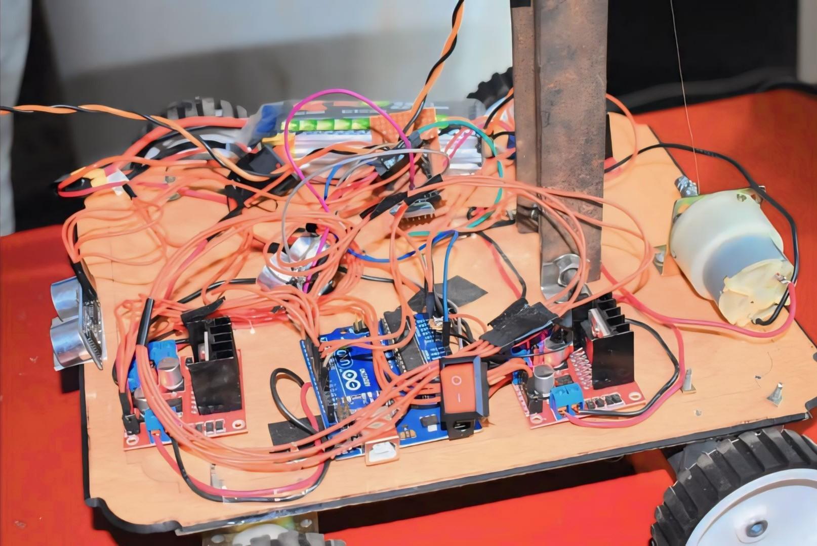
Project Overview
An articulated robotic hand capable of mimicking human hand movements with precision and dexterity.
Technical Analysis
Powered by NRC AIAs a robotics and electronics expert, I'm delighted to provide a detailed technical analysis for your "Moving Robotic Hand" project. This project is an excellent foundation for learning about mechatronics, control systems, and basic biomimicry.
Moving Robotic Hand: Detailed Technical Analysis
article1. Technical Overview
The "Moving Robotic Hand" project aims to create an articulated robotic hand that can replicate human hand movements. This involves integrating mechanical design, electronic control, and programming to achieve precise and dexterous motion.
Core Principles:
- Biomimicry: The design mimics the skeletal structure and tendon-muscle system of a human hand.
- Actuation: Small servo motors act as "muscles," pulling "tendons" (strings or fishing lines) to bend the finger joints.
- Articulation: Each finger consists of multiple segments (phalanges) connected by hinges, allowing for bending motion. Springs or elastic bands are used to provide a "return" force, pulling the fingers back to an open position when the tendons are relaxed.
- Control System: A microcontroller (e.g., Arduino) serves as the "brain," receiving commands (either pre-programmed sequences or sensor inputs) and translating them into precise angular positions for each servo motor.
- Precision & Dexterity: By individually controlling multiple servo motors connected to different finger segments, the hand can achieve a range of gestures, from a simple grasp to more complex movements. The precision depends on the servo resolution and the mechanical design's tolerances.
How it Works Technically:
- Mechanical Structure: The hand typically consists of 3D-printed or laser-cut parts forming the palm, wrist, and individual finger segments (proximal, intermediate, distal phalanges). These segments are hinged together using pins or small bolts.
- Tendon System: A strong, low-friction line (like fishing line or dental floss) is routed from the tip of each finger, through guides along the finger segments, and then connected to the horn of a servo motor mounted in the palm or wrist area. When a servo rotates, it pulls the line, causing the finger to curl.
- Return Mechanism: To open the hand, springs (e.g., small coil springs or elastic bands) are strategically placed on the finger joints. When the servo relaxes its pull, these springs extend the finger back to its open position.
- Actuation: Miniature servo motors (one per finger or even one per joint for advanced dexterity) are chosen for their precise angular control (typically 0-180 degrees) and relatively low cost. Each servo is connected to a specific tendon.
- Microcontroller Control: An Arduino board reads control signals. For a basic hand, these signals might be pre-programmed sequences of servo angles. For advanced mimicry, flex sensors worn on a human hand can provide analog input, which the Arduino then maps to the corresponding servo angles.
- Power Management: Servo motors draw significant current, especially when stalled or under load. A separate, robust power supply is crucial for the servos to prevent brownouts or damage to the microcontroller. The microcontroller and servos must share a common ground.
article2. Components Required
Here's a comprehensive list of components, assuming a 5-finger articulated hand (four fingers + thumb):
label_importantMechanical Components:
- 3D Printed Parts:
- Palm/Hand Base
- 5 x Finger Assemblies (each with multiple phalanges and possibly a fingertip)
- Wrist/Servo Mount Housing
- Optional: Stand/Base for the hand
- Tendons:
- High-strength Fishing Line or Braided Dental Floss (approx. 10-20 meters, depending on design and redundancy)
- Return Mechanism:
- Small Extension Springs or Elastic Bands (5-10 pieces, one or two per finger joint)
- Fasteners:
- Small Screws (e.g., M2 or M3, various lengths for mounting servos and assembling parts)
- Small Bolts and Nuts (for finger hinges, if not 3D printed pins)
- Shaft Collars or small O-rings (to prevent tendons from slipping off servo horns)
label_importantElectronic Components:
- Microcontroller:
- Arduino Mega 2560: Recommended due to its numerous digital I/O pins (especially PWM pins for servos) and analog input pins (for sensors).
- (Alternative: Arduino Uno if using fewer servos or an external servo driver board.)
- Actuators:
- SG90 Micro Servo Motors (x 5 or more): Lightweight, affordable, good for basic movements. (Torque: 1.8 kg-cm)
- (Alternative: MG996R or MG90S Metal Gear Servos for more torque and durability, especially for larger hands or if grasping heavier objects.)
- Sensors (Optional - for mimicking human hand):
- Flex Sensors (x 5 or more): One per finger or per finger joint for detailed mimicry (e.g., 2.2-inch or 4.5-inch).
- Resistors (x 5 or more): 10 kOhm or 22 kOhm, for building voltage dividers with flex sensors.
- Power Management:
- External 5V Power Supply: Dedicated power supply for servos (e.g., a 5V/3A or 5V/5A DC power adapter, or a UBEC/buck converter if using a higher voltage source like a LiPo battery). Arduino's onboard 5V regulator cannot supply enough current for multiple servos.
- Breadboard Power Module (Optional): If using a breadboard for distribution.
- Electrolytic Capacitor (Optional): 100uF-470uF, placed across the servo power lines near the servos to smooth out power fluctuations.
- Interfacing:
- Breadboard (Full-size): For organizing connections and voltage dividers.
- Jumper Wires: Male-to-male, male-to-female, various lengths.
- Servo Extension Cables (Optional): If servos are far from the Arduino.
- Miscellaneous:
- USB Cable (Type B): For programming the Arduino.
- Soldering Iron & Solder: For permanent connections if preferred.
- Heat Shrink Tubing/Electrical Tape: For insulation.
- Small Zip Ties: For cable management.
article3. Circuit Diagram Description
We'll describe the circuit for an Arduino Mega, 5 SG90 servos, and 5 flex sensors (as an optional extension for mimicry).
Key Principles:
- Separate Power for Servos: Servos draw significant current. Connecting them directly to the Arduino's 5V pin can overload the onboard regulator, leading to unstable behavior (e.g., servo jitter, Arduino resets).
- Common Ground: The ground (GND) of the external power supply, the Arduino, and all components must be connected together to establish a common reference point.
- PWM Pins for Servos: Servos require Pulse Width Modulation (PWM) signals for control. On the Arduino Mega, pins 2-13 and 44-46 support PWM.
- Analog Pins for Flex Sensors: Flex sensors are analog devices; their resistance changes with bending. This change is converted to a voltage using a voltage divider circuit, which is read by Arduino's Analog Input pins (A0-A15).
Connections (Simplified Diagram Description):
-
Arduino Mega Power:
- Connect the Arduino Mega to your computer via USB for programming and initial power.
- Alternatively, use a 7-12V DC power adapter connected to the Arduino's barrel jack for standalone operation.
-
External Servo Power Supply (e.g., 5V/3A Adapter):
- Positive (+5V) Output: Connect to the positive power rail of your breadboard.
- Negative (GND) Output: Connect to the negative (GND) power rail of your breadboard.
- Crucial: Connect the negative (GND) rail of the breadboard to one of the GND pins on the Arduino Mega. This establishes a common ground.
-
Servo Motor Connections (x 5):
- Each SG90 servo has three wires:
- Brown/Darkest Wire (GND): Connect to the common GND rail on the breadboard.
- Red/Middle Wire (VCC): Connect to the +5V power rail on the breadboard (from the external power supply).
- Orange/Lightest Wire (Signal): Connect to a Digital PWM pin on the Arduino Mega.
- Servo 1 (Thumb): Signal to Arduino Pin D2
- Servo 2 (Index): Signal to Arduino Pin D3
- Servo 3 (Middle): Signal to Arduino Pin D4
- Servo 4 (Ring): Signal to Arduino Pin D5
- Servo 5 (Pinky): Signal to Arduino Pin D6 (You can use any available PWM pins, but using consecutive pins simplifies code.)
- Each SG90 servo has three wires:
-
Flex Sensor Connections (x 5 - Optional for mimicry):
- Each flex sensor requires a Voltage Divider circuit to convert resistance change into a voltage change that the Arduino can read.
- For each Flex Sensor:
- Connect one end of the Flex Sensor to the Arduino's +5V pin (or the +5V rail of the breadboard, if supplied by Arduino's 5V out).
- Connect the other end of the Flex Sensor in series with a 10kOhm Resistor.
- Connect the other end of the 10kOhm Resistor to the common GND rail on the breadboard.
- Take the Analog Output from the point between the Flex Sensor and the 10kOhm Resistor. Connect this point to an Analog Input pin on the Arduino.
- Flex Sensor 1 (Thumb): Analog Output to Arduino Pin A0
- Flex Sensor 2 (Index): Analog Output to Arduino Pin A1
- Flex Sensor 3 (Middle): Analog Output to Arduino Pin A2
- Flex Sensor 4 (Ring): Analog Output to Arduino Pin A3
- Flex Sensor 5 (Pinky): Analog Output to Arduino Pin A4
Conceptual Circuit Diagram:
+-----------------------------+ | | | ARDUINO MEGA 2560 | | | +-------+ | GND ---+ | | External | 5V Out +--------->| | | | 5V Power | | | +---|--------------+ | Supply | | | | | +-------+ | | | | | | | | | | +--+---+------------------+ | | | (Common Ground Bus) | | | | | | | +------------------------+ | | | | | +------>| +5V (Power Bus for Servos) | | | | | +------------------------+ | | | | | | | | | Servo Signal Lines: | | | | D2 <----------------- (Orange) Servo 1 (Thumb) | D3 <----------------- (Orange) Servo 2 (Index) | D4 <----------------- (Orange) Servo 3 (Middle) | D5 <----------------- (Orange) Servo 4 (Ring) | D6 <----------------- (Orange) Servo 5 (Pinky) | | | Analog Input Lines (Optional Flex Sensors): | | | A0 <----------------- Flex Sensor 1 Analog Out | A1 <----------------- Flex Sensor 2 Analog Out | A2 <----------------- Flex Sensor 3 Analog Out | A3 <----------------- Flex Sensor 4 Analog Out | A4 <----------------- Flex Sensor 5 Analog Out | | +-------------------------------------------+ | (Brown/Black) Servo GND to Common GND | (Red) Servo VCC to +5V Servo Power Bus | | Flex Sensor Voltage Divider: | +5V (from Arduino 5V) | | | Flex Sensor | | |---------+------------------> Analog Pin (e.g., A0) | | | 10kOhm Resistor | | | GND (to Common Ground Bus)
article4. Source Code
This code provides a basic pre-programmed sequence for the robotic hand. I'll include a conceptual
loop()Programming Language: C++ (Arduino IDE)
C++// -------------------------------------------------------------------------- // Project: Moving Robotic Hand // Description: Controls an articulated robotic hand using servo motors // to perform pre-programmed gestures. // Microcontroller: Arduino Mega 2560 (or Arduino Uno with fewer servos/servo driver) // Author: Your Name / Robotics Expert // Date: October 26, 2023 // -------------------------------------------------------------------------- // 1. Include Libraries // The Servo library is essential for controlling servo motors. #include <Servo.h> // 2. Define Pin Assignments // Assign Arduino digital PWM pins to each servo motor. // Using pins 2-6 on Arduino Mega. const int thumbServoPin = 2; const int indexServoPin = 3; const int middleServoPin = 4; const int ringServoPin = 5; const int pinkyServoPin = 6; // Define Analog Pins for optional Flex Sensors (if implementing mimicry) // For now, these are commented out if not used for initial pre-programmed sequence. // const int thumbFlexSensorPin = A0; // const int indexFlexSensorPin = A1; // const int middleFlexSensorPin = A2; // const int ringFlexSensorPin = A3; // const int pinkyFlexSensorPin = A4; // 3. Create Servo Objects // Create an instance of the Servo class for each finger. Servo thumbServo; Servo indexServo; Servo middleServo; Servo ringServo; Servo pinkyServo; // 4. Define Servo Angle Ranges (Calibration Values) // These values are highly dependent on your specific mechanical design, // servo mounting, and tendon routing. You will need to calibrate these. // A common range for SG90 servos is 0-180 degrees. // 'open' position: fingers extended // 'closed' position: fingers curled (grasping) // Ensure these values don't cause physical strain on the hand mechanism. // Example angles for fully open hand const int ANGLE_OPEN_THUMB = 90; // Thumb might have a different range/orientation const int ANGLE_OPEN_INDEX = 0; const int ANGLE_OPEN_MIDDLE = 0; const int ANGLE_OPEN_RING = 0; const int ANGLE_OPEN_PINKY = 0; // Example angles for a 'fist' (curled fingers) const int ANGLE_CLOSED_THUMB = 180; // Example, adjust for actual thumb curl const int ANGLE_CLOSED_INDEX = 180; const int ANGLE_CLOSED_MIDDLE = 180; const int ANGLE_CLOSED_RING = 180; const int ANGLE_CLOSED_PINKY = 180; // Example angles for a 'point' gesture const int ANGLE_POINT_THUMB = 120; // Slightly curled thumb const int ANGLE_POINT_INDEX = 0; // Index finger extended const int ANGLE_POINT_MIDDLE = 180; // Other fingers curled const int ANGLE_POINT_RING = 180; const int ANGLE_POINT_PINKY = 180; // 5. Setup Function - Runs once when the Arduino starts void setup() { // Initialize serial communication for debugging purposes. Serial.begin(9600); Serial.println("Robotic Hand Project - Starting Up..."); // Attach each servo object to its respective pin. // This tells the Arduino which pin will control which servo. thumbServo.attach(thumbServoPin); indexServo.attach(indexServoPin); middleServo.attach(middleServoPin); ringServo.attach(ringServoPin); pinkyServo.attach(pinkyServoPin); // Set initial position for all servos. // It's good practice to move them to a known 'open' state to avoid collisions. setAllFingers(ANGLE_OPEN_THUMB, ANGLE_OPEN_INDEX, ANGLE_OPEN_MIDDLE, ANGLE_OPEN_RING, ANGLE_OPEN_PINKY); Serial.println("Hand initialized to open position."); delay(1000); // Wait for a second for fingers to settle } // 6. Loop Function - Runs repeatedly after setup() void loop() { // --- Pre-programmed Gesture Sequence --- // This section demonstrates a series of predefined hand movements. // Each movement is called as a function, followed by a delay. Serial.println("Performing 'Make a Fist' gesture..."); makeFist(); delay(2000); // Hold for 2 seconds Serial.println("Performing 'Open Hand' gesture..."); openHand(); delay(2000); // Hold for 2 seconds Serial.println("Performing 'Point' gesture..."); pointFinger(); delay(2000); // Hold for 2 seconds Serial.println("Performing 'Wave' gesture..."); waveHand(); delay(3000); // Hold for 3 seconds Serial.println("Returning to 'Open Hand' gesture..."); openHand(); delay(2000); // Hold for 2 seconds // Add more gestures or patterns here as needed. } // 7. Helper Functions for Hand Control /** * @brief Sets all fingers to specific angles simultaneously. * @param thumbAngle Angle for the thumb servo. * @param indexAngle Angle for the index finger servo. * @param middleAngle Angle for the middle finger servo. * @param ringAngle Angle for the ring finger servo. * @param pinkyAngle Angle for the pinky finger servo. */ void setAllFingers(int thumbAngle, int indexAngle, int middleAngle, int ringAngle, int pinkyAngle) { thumbServo.write(thumbAngle); indexServo.write(indexAngle); middleServo.write(middleAngle); ringServo.write(ringAngle); pinkyServo.write(pinkyAngle); } /** * @brief Makes the robotic hand form a fist. * Adjust ANGLE_CLOSED_X constants above for proper calibration. */ void makeFist() { // Move fingers sequentially or simultaneously for a more natural look. // Here, we'll move them simultaneously to the closed position. setAllFingers(ANGLE_CLOSED_THUMB, ANGLE_CLOSED_INDEX, ANGLE_CLOSED_MIDDLE, ANGLE_CLOSED_RING, ANGLE_CLOSED_PINKY); } /** * @brief Opens the robotic hand. * Adjust ANGLE_OPEN_X constants above for proper calibration. */ void openHand() { setAllFingers(ANGLE_OPEN_THUMB, ANGLE_OPEN_INDEX, ANGLE_OPEN_MIDDLE, ANGLE_OPEN_RING, ANGLE_OPEN_PINKY); } /** * @brief Makes the robotic hand point with the index finger. * Adjust ANGLE_POINT_X constants above for proper calibration. */ void pointFinger() { setAllFingers(ANGLE_POINT_THUMB, ANGLE_POINT_INDEX, ANGLE_POINT_MIDDLE, ANGLE_POINT_RING, ANGLE_POINT_PINKY); } /** * @brief Performs a simple waving motion. * This function demonstrates a sequence of movements. */ void waveHand() { // A simple back-and-forth motion with fingers relatively open int waveAngle = ANGLE_OPEN_INDEX / 2; // Slightly curl fingers for wave effect // Example: curl all fingers slightly thumbServo.write(ANGLE_OPEN_THUMB); // Thumb stays relatively open indexServo.write(waveAngle); middleServo.write(waveAngle); ringServo.write(waveAngle); pinkyServo.write(waveAngle); delay(500); // Example: open all fingers openHand(); delay(500); // Repeat the curl and open a few times for (int i = 0; i < 3; i++) { indexServo.write(waveAngle + 30); // Slightly more curl for wave accent middleServo.write(waveAngle + 30); ringServo.write(waveAngle + 30); pinkyServo.write(waveAngle + 30); delay(300); openHand(); delay(300); } } /* // --- Alternative Loop Function for Flex Sensor Input (Requires Sensor Hardware) --- // Uncomment this 'loop()' function and comment out the pre-programmed one above // if you have flex sensors connected and calibrated. void loop() { // Read sensor values int thumbSensorVal = analogRead(thumbFlexSensorPin); int indexSensorVal = analogRead(indexFlexSensorPin); int middleSensorVal = analogRead(middleFlexSensorPin); int ringSensorVal = analogRead(ringFlexSensorPin); int pinkySensorVal = analogRead(pinkyFlexSensorPin); // Map sensor values to servo angles // Flex sensors typically output lower values when bent, higher when straight. // Adjust these 'map' ranges (input_min, input_max, output_min, output_max) // based on your sensor's actual readings for fully straight vs. fully bent states. // 'constrain' ensures the mapped value stays within the servo's physical range (0-180). int thumbAngle = map(thumbSensorVal, 400, 700, ANGLE_CLOSED_THUMB, ANGLE_OPEN_THUMB); // Example ranges int indexAngle = map(indexSensorVal, 400, 700, ANGLE_CLOSED_INDEX, ANGLE_OPEN_INDEX); int middleAngle = map(middleSensorVal, 400, 700, ANGLE_CLOSED_MIDDLE, ANGLE_OPEN_MIDDLE); int ringAngle = map(ringSensorVal, 400, 700, ANGLE_CLOSED_RING, ANGLE_OPEN_RING); int pinkyAngle = map(pinkySensorVal, 400, 700, ANGLE_CLOSED_PINKY, ANGLE_OPEN_PINKY); // Constrain angles to servo's operational range (0-180 degrees) thumbAngle = constrain(thumbAngle, 0, 180); indexAngle = constrain(indexAngle, 0, 180); middleAngle = constrain(middleAngle, 0, 180); ringAngle = constrain(ringAngle, 0, 180); pinkyAngle = constrain(pinkyAngle, 0, 180); // Write mapped angles to servos setAllFingers(thumbAngle, indexAngle, middleAngle, ringAngle, pinkyAngle); // Optional: Print sensor values and servo angles for debugging Serial.print("Thumb: S="); Serial.print(thumbSensorVal); Serial.print(", A="); Serial.print(thumbAngle); Serial.print(" | Index: S="); Serial.print(indexSensorVal); Serial.print(", A="); Serial.print(indexAngle); Serial.println(); // New line for next set of readings delay(20); // Small delay to prevent too rapid updates and smooth motion } */
article5. Source Code Structure
The provided source code follows a standard Arduino sketch structure, which is C++ based.
Main Code Modules:
- Header Inclusion (directives): At the very top, necessary libraries are included.
#includeis fundamental for this project.Servo.h - Pin Definitions (): Global constants are used to define which Arduino pins are connected to specific components (servos, and optionally sensors). This makes the code easier to read and modify.
const int - Servo Object Instantiation (objects): An instance of the
Servoclass is created for each servo motor. These objects are used to control the respective motors.Servo - Calibration Values (): Constants define the specific servo angles that correspond to "open," "closed," or other specific positions for each finger. These are crucial for proper movement and require careful calibration after hardware assembly.
const int ANGLE_... - Function: This is the initialization routine. It runs only once when the Arduino powers on or resets.
setup()- Initializes serial communication for debugging.
- Attaches each object to its assigned digital PWM pin.
Servo - Sets the initial position of the robotic hand.
- Function: This is the main program loop. It runs continuously after
loop()completes.setup()- In the provided code, it calls a sequence of pre-defined gesture functions.
- (If using flex sensors, this is where sensor readings would be taken, mapped to servo angles, and then written to the servos.)
- Helper Functions (e.g., ,
setAllFingers,makeFist,openHand,pointFinger): These are custom functions defined by the user to encapsulate specific actions or sequences. This modularizes the code, making it cleaner and more readable.waveHand
Libraries Needed:
- : This is the only mandatory library for basic servo control. It is a standard library usually included by default in the Arduino IDE. If not, you can find it in
Servo.hor manually add it.Sketch > Include Library > Manage Libraries...
Key Functions Used:
- : Initializes serial communication at a specified baud rate for sending debugging messages to the Serial Monitor.
Serial.begin(speed) - : Prints data to the Serial Monitor, followed by a new line.
Serial.println(data) - : A method of the
servoName.attach(pin)object that associates a servo motor with a specific Arduino PWM pin.Servo - : A method of the
servoName.write(angle)object that rotates the servo motor to a specified angle (0-180 degrees).Servo - : Pauses the program for a specified number of milliseconds. Used to control the timing of gestures.
delay(milliseconds) - : Reads the value from the specified analog input pin (0 to 1023). Used for reading flex sensor data.
analogRead(pin) - : Re-maps a number from one range to another. Essential for converting sensor readings (e.g., 0-1023) to servo angles (e.g., 0-180).
map(value, fromLow, fromHigh, toLow, toHigh) - : Constrains a number to be within a specified range. Used to ensure mapped servo angles do not exceed the physical limits of the servo.
constrain(value, min, max)
article6. Step-by-Step Implementation Guide
label_importantA. Hardware Assembly Steps:
- 3D Print Hand Components:
- Print all parts: palm, finger segments (proximal, intermediate, distal), fingertips, and servo mounts. Ensure good print quality, especially for hinges and tendon channels.
- Assemble Finger Joints:
- Connect the phalanges for each finger using small pins or bolts to create the hinge joints. Ensure smooth movement.
- Attach the return springs/elastic bands to each finger joint. These should provide enough tension to fully open the finger when the tendon is relaxed.
- Mount Servos:
- Securely mount the SG90 (or chosen) servo motors into the designated slots within the palm or wrist structure. Ensure their horns face the correct direction for tendon routing.
- Route Tendons:
- For each finger, tie one end of the fishing line/dental floss to the fingertip (or the distal phalanx).
- Carefully thread the line through the guides/channels along each finger segment, making sure it can glide smoothly without friction.
- Continue routing the line through channels in the palm structure towards the corresponding servo motor.
- Attach the other end of the line to the horn of its respective servo. A small knot secured with super glue or a small shaft collar/O-ring can help prevent slipping.
- Crucial: Adjust tendon tension. Fingers should be fully extended when servos are at their "open" angle (e.g., 0 degrees) and fully curled when at their "closed" angle (e.g., 180 degrees). This will require trial and error with the servo angles and tendon length.
- Mount Arduino and Breadboard:
- Secure the Arduino Mega and breadboard to the base or a convenient part of the hand assembly using screws or standoffs.
- Wire Components (refer to Circuit Diagram Description):
- External Power Supply: Connect the 5V external power supply to the breadboard's power rails.
- Common Ground: Connect the GND of the external power supply's rail on the breadboard to one of the GND pins on the Arduino Mega. This is very important.
- Servos:
- Connect the Brown/GND wire of each servo to the common GND rail.
- Connect the Red/VCC wire of each servo to the +5V power rail (from the external supply).
- Connect the Orange/Signal wire of each servo to its assigned Arduino PWM pin (D2-D6).
- Flex Sensors (if used):
- For each sensor, set up the voltage divider on the breadboard:
- One end of flex sensor to Arduino 5V.
- Other end of flex sensor in series with a 10kOhm resistor to GND.
- Connect the point between the flex sensor and resistor to its assigned Arduino Analog pin (A0-A4).
- For each sensor, set up the voltage divider on the breadboard:
- Final Checks: Double-check all wiring for correct polarity and connections before powering up.
label_importantB. Software Setup and Programming:
- Install Arduino IDE: If you haven't already, download and install the Arduino IDE from the official Arduino website.
- Install Libraries:
- The library is usually pre-installed. If not, go to
Servo.hand search for "Servo."Sketch > Include Library > Manage Libraries...
- The
- Copy and Paste Code: Open a new sketch in the Arduino IDE and copy the provided source code into it.
- Select Board and Port:
- Go to and select "Arduino Mega 2560" (or "Arduino Uno" if using that board).
Tools > Board - Go to and select the serial port corresponding to your Arduino board.
Tools > Port
- Go to
- Verify and Upload Code:
- Click the "Verify" button (checkmark icon) to compile the code and check for errors.
- If compilation is successful, click the "Upload" button (right arrow icon) to upload the code to your Arduino board.
- Open Serial Monitor: Click the "Serial Monitor" icon (magnifying glass) to view debugging messages from your Arduino. Ensure the baud rate matches in the code.
Serial.begin(9600)
label_importantC. Testing and Calibration Procedures:
- Initial Power-Up and Jitter Check:
- After uploading, observe the servos. They might twitch or move to their initial programmed position.
- If there's excessive jitter, ensure your external power supply is robust enough and all grounds are common. Adding a large capacitor (100uF-470uF) across the servo power rails on the breadboard can help.
- Servo Angle Calibration (Crucial!):
- The and
ANGLE_OPEN_Xconstants in the code are placeholder values. Your hand's physical design will dictate the actual angles.ANGLE_CLOSED_X - Start by manually adjusting the values for each servo in the
write()function (e.g.,setup()). Upload, observe, and tweak.thumbServo.write(90); - The goal is to find the angle that makes a finger fully extended (0 degrees, or whatever value opens it fully) and another angle that makes it fully curled (180 degrees, or whatever value curls it fully).
- Use the Serial Monitor to print current servo angles and experiment.
- Mechanical Adjustment: Sometimes, fine-tuning the tendon length or the servo horn position (by removing and re-attaching it) is necessary in conjunction with software angle calibration.
- The
- Test Individual Finger Movements:
- Create a temporary function or modify to control one finger at a time. For example:
loop()C++// In loop() indexServo.write(ANGLE_OPEN_INDEX); delay(1000); indexServo.write(ANGLE_CLOSED_INDEX); delay(1000); - Verify each finger moves smoothly through its full intended range without binding or excessive strain.
- Create a temporary function or modify
- Test Full Sequences:
- Once individual fingers are calibrated, test the ,
makeFist(),openHand(), andpointFinger()functions.waveHand() - Adjust values to control the speed and rhythm of movements.
delay()
- Once individual fingers are calibrated, test the
- Flex Sensor Calibration (if used):
- With the uncommented, open the Serial Monitor.
flex sensor loop() - Observe the values when your human hand (with flex sensors) is fully straight and then fully bent. Note these min/max values for each sensor.
analogRead() - Update the function's
map()andfromLowparameters for each sensor based on these observed min/max values.fromHigh - Adjust and
toLowintoHighto match the calibratedmap()andANGLE_CLOSED_Xfor your robotic hand.ANGLE_OPEN_X - Continually test and refine until the robotic hand mimics your hand movements accurately.
- With the
article7. Challenges and Solutions
Students undertaking this project may encounter several common issues:
- Challenge: Servo Jitter or Weak Movement:
- Problem: Servos twitch uncontrollably, vibrate, or lack the strength to move the fingers properly.
- Solution:
- Insufficient Power: The most common cause. Ensure you are using an external, dedicated 5V power supply for the servos, not powering them directly from the Arduino's 5V pin. The Arduino's onboard regulator can't supply enough current for multiple servos, leading to voltage drops.
- Common Ground: Double-check that the GND of your external power supply, Arduino, and all components are connected to a single common ground point.
- Power Filtering: Add a large electrolytic capacitor (100uF to 470uF, 16V or more) across the +5V and GND rails of your servo power distribution on the breadboard. This helps smooth out voltage spikes and drops caused by servo movement.
- Servo Quality/Torque: SG90s are small. If the hand mechanism is stiff or heavy, they might not be strong enough. Consider upgrading to stronger servos like MG90S (mini metal gear) or MG996R (standard metal gear).
- Tendon Friction: Ensure tendons run smoothly through channels without rubbing.
- Challenge: Finger Movement Not Smooth or Full Range:
- Problem: Fingers might get stuck, not fully open/close, or move in a jerky fashion.
- Solution:
- Mechanical Friction: Check all hinge joints for smoothness. Sanding or filing 3D-printed parts might be necessary. Apply a little lubricant (silicone grease).
- Tendon Routing: Ensure tendon lines are not snagging on anything, are routed cleanly, and are not too tight or too loose.
- Return Mechanism: Verify that springs/elastic bands provide enough force to fully extend the fingers when the tendon is relaxed. If not, use stronger springs or add more.
- Servo Calibration: The servo angles need to be precisely calibrated for the physical limits of your specific hand. Adjust
write()andANGLE_OPEN_Xvalues.ANGLE_CLOSED_X - Servo Range: Some servos might not reach true 0 or 180 degrees. Adjust parameters (if using sensors) or
map()values accordingly.write()
- Challenge: Tendons Snapping or Slipping:
- Problem: The fishing line breaks, or the knot comes undone from the servo horn or fingertip.
- Solution:
- Material Strength: Use strong, braided fishing line (e.g., 20-30 lb test) or high-strength dental floss. Avoid monofilament if it shows signs of stretching or breaking.
- Secure Knots: Tie strong, self-tightening knots (e.g., fisherman's knot, arbor knot) and reinforce with a tiny drop of super glue on the knot only.
- Attachment Points: Ensure the attachment points on the fingertips and servo horns are robust and don't have sharp edges that could fray the line.
- Tension Management: Do not over-tension the tendons when calibrating. Only pull as much as needed for full movement to avoid undue stress on the line and servo.
- Challenge: Flex Sensor Readings Are Inaccurate or Unstable:
- Problem: Robotic hand doesn't mimic human hand correctly, or movements are erratic.
- Solution:
- Voltage Divider: Ensure the flex sensor is correctly wired in a voltage divider configuration with a pull-down resistor (e.g., 10kOhm). The resistor value affects the sensitivity. Experiment with 10kOhm or 22kOhm.
- Calibration: This is crucial. Read the values when the flex sensor is truly straight and truly bent. Use these specific min/max values for your
analogRead()function.map() - Noise: Analog readings can be noisy. Take multiple readings and average them (e.g., 10 times and sum/average) to smooth the input.
analogRead(pin) - Sensor Adherence: Ensure the flex sensor is securely taped/glued to your finger in a way that accurately reflects its bend.
- Challenge: Code Bugs or Compilation Errors:
- Problem: Code doesn't compile, or the logic is flawed.
- Solution:
- Syntax Check: Arduino IDE's "Verify" button (checkmark) will highlight syntax errors. Read the error messages carefully; they usually point to the line number and type of error.
- Pin Assignments: Double-check that your pin definitions match your physical wiring.
const int - Library Inclusion: Ensure is correctly included at the top of your sketch.
Servo.h - Serial Monitor Debugging: Use and
Serial.print()extensively to print variable values (like sensor readings, mapped angles) at different points in yourSerial.println()function. This helps you understand what the code is doing internally.loop()
article8. Learning Outcomes
Completing the "Moving Robotic Hand" project provides students with a rich, hands-on learning experience across multiple engineering disciplines:
- Robotics Fundamentals:
- Understanding of actuators (servo motors) and their control.
- Basic concepts of kinematics (how the movement of one joint affects the whole system).
- Introduction to tendon-driven systems in robotics.
- The importance of mechanical design in robotic functionality.
- Electronics & Microcontrollers:
- Interfacing servo motors with a microcontroller.
- Power management for multiple high-current components (servos).
- Understanding of sensor integration (flex sensors) and analog-to-digital conversion.
- Practical application of voltage divider circuits.
- Working with the Arduino ecosystem (IDE, libraries, board programming).
- Programming (C++ for Arduino):
- Writing structured and commented code.
- Using libraries ().
Servo.h - Implementing control logic (sequential movements, mapping sensor inputs).
- Debugging techniques using .
Serial.print() - Utilizing essential functions like ,
map(),constrain(),delay().analogRead()
- Mechanical Design & Fabrication:
- Practical experience with 3D printing for creating custom mechanical parts.
- Understanding of articulated joint design and assembly.
- Considerations for friction, tension, and return mechanisms.
- Problem-Solving & Systems Integration:
- Identifying and troubleshooting issues that arise from the interaction of mechanical, electrical, and software components.
- The iterative process of design, build, test, and refine.
- Developing skills in calibration to achieve desired performance.
- Biomimicry: Understanding how biological systems can inspire engineering designs.
article9. Extensions and Improvements
This project serves as an excellent starting point. Here are several ways to extend and enhance the robotic hand:
- Advanced Actuation & Degrees of Freedom (DoF):
- More Servos per Finger: Instead of one servo per finger, use two or three per finger to control individual phalanges, mimicking the human hand's multiple joints (e.g., controlling metacarpophalangeal and proximal interphalangeal joints independently).
- Wrist Movements: Add servos for wrist flexion/extension, ulnar/radial deviation, and pronation/supination to increase overall hand dexterity.
- Thumb Abduction/Adduction: Implement a separate mechanism for the thumb to move away from/towards the palm.
- Improved Dexterity & Grasping:
- Force/Pressure Sensors: Integrate FSRs (Force Sensitive Resistors) or load cells on fingertips to detect contact and grasp strength. Use this feedback for a more adaptive grip (e.g., stop squeezing when enough force is detected).
- Grasping Algorithms: Implement more sophisticated algorithms to dynamically adjust finger positions for different object shapes and sizes.
- Enhanced User Input & Control:
- Haptic Feedback: Incorporate small vibration motors or linear resonant actuators (LRAs) into a human control glove to provide tactile feedback to the user when the robotic hand makes contact or grips an object.
- Wireless Control: Add a Bluetooth (HC-05/06) or Wi-Fi (ESP8266) module for remote control from a smartphone app, PC, or another microcontroller.
- Joystick/Potentiometer Control: Create a more intuitive physical controller with joysticks or potentiometers for direct finger control.
- Gesture Recognition (ML/AI): Use accelerometers/gyroscopes on the human hand and train a machine learning model (e.g., TinyML on Arduino Nano 33 BLE Sense) to recognize specific hand gestures and trigger corresponding robotic hand movements.
- Advanced Sensing & Autonomy:
- Object Detection: Integrate a small camera module (e.g., ESP32-CAM, OpenMV) and use image processing to detect and identify objects before grasping.
- Vision-Based Control: Use visual feedback to guide the hand's approach and grasp.
- IMU for Orientation: Add an Inertial Measurement Unit (IMU) like MPU6050 to the robotic hand's wrist to understand its own orientation in space.
- Software & Control System Enhancements:
- Non-Blocking Code: Replace with
delay()for non-blocking timing, allowing multiple tasks to run concurrently (e.g., reading sensors while moving servos).millis() - Inverse Kinematics: For highly articulated hands, implement inverse kinematics to calculate the required joint angles to reach a specific fingertip position in 3D space. This is a complex but powerful extension.
- PID Control: For more precise and stable servo positioning, especially under load, implement a Proportional-Integral-Derivative (PID) control loop.
- Non-Blocking Code: Replace
- Mechanical Design Improvements:
- Flexible Phalanges: Experiment with flexible 3D printing filaments (e.g., TPU) for finger segments to allow for more compliant grasping and reduced risk of breaking.
- Worm Gear/Planetary Gear Servos: For higher torque and smoother motion without backlash, consider using hobby servos with integrated gearboxes or even small stepper motors with drivers for more precise control (though more complex).
- Cable Routing/Concealment: Design channels to hide wires and tendons for a cleaner aesthetic and better protection.
- Application Development:
- Teleoperation: Create a full teleoperation system where human hand movements are accurately mirrored by the robot in real-time.
- Robotic Gripper for Automation: Adapt the hand for specific industrial or domestic grasping tasks.
By exploring these extensions, students can delve deeper into advanced robotics, control theory, machine learning, and human-robot interaction, pushing the boundaries of their initial robotic hand project.
infoThis analysis is generated by AI and should be used as a learning guide. Always verify technical details.