


Ball Playing Robot
Ball Playing Robot is an autonomous engineering project developed by the NIST Robotics Club (NRC) at NIST University, Berhampur. A robot designed to detect, track, and interact with balls, demonstrating advanced object recognition capabilities.

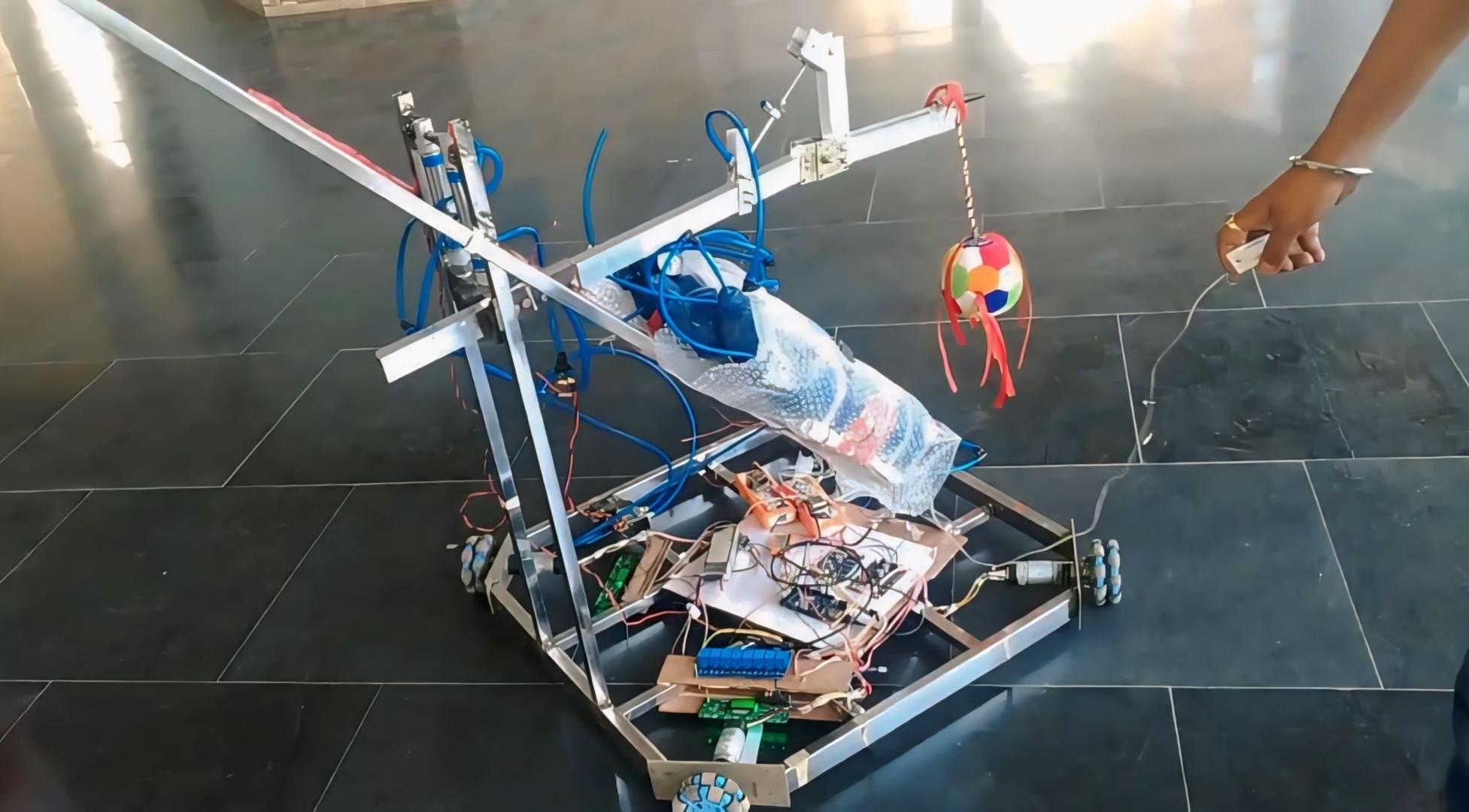
Project Overview
A robot designed to detect, track, and interact with balls, demonstrating advanced object recognition capabilities.
Technical Analysis
Powered by NRC AIThis comprehensive guide details the technical aspects of building a "Ball Playing Robot," designed to detect, track, and interact with balls using advanced object recognition. This project is ideal for engineering students seeking to apply principles of robotics, electronics, and computer vision.
articleBall Playing Robot: Detailed Technical Analysis
label_important1. Technical Overview
The "Ball Playing Robot" is an autonomous mobile robot that leverages computer vision to identify and follow a ball, culminating in an interaction. The project integrates several key technical domains:
- Sensing (Vision System): A camera (e.g., Raspberry Pi Camera Module) captures video frames of the environment. These frames are processed using computer vision techniques to detect the ball. The primary method for detection will be color-based segmentation (e.g., identifying a red or blue ball using HSV color space thresholds), followed by contour detection and circle fitting. The robot extracts key information like the ball's centroid (x, y coordinates) and its approximate size (area).
- Processing (Control System): A single-board computer (SBC), typically a Raspberry Pi, acts as the central brain. It receives the video stream, executes the computer vision algorithms to locate the ball, and then calculates the necessary robot movements. A basic feedback control loop (e.g., a Proportional (P) controller or a full Proportional-Integral-Derivative (PID) controller) is used to guide the robot. The controller's goal is to keep the ball centered in the camera's field of view and maintain an optimal distance for interaction.
- Actuation (Locomotion System): The robot utilizes a differential drive system, comprising two or four DC geared motors. A motor driver (H-bridge) translates the control signals from the Raspberry Pi into appropriate voltage and current to drive the motors. By independently controlling the speed and direction of each motor, the robot can move forward, backward, turn, and pivot.
- Interaction Mechanism (Optional): Once the robot is in close proximity to the ball, an additional actuator (e.g., a servo motor controlling a kicking mechanism) can be triggered to "play" with the ball, such as kicking it away or pushing it.
Workflow:
- Image Acquisition: The camera continuously captures frames.
- Pre-processing & Filtering: Frames are converted to HSV color space, and noise is reduced.
- Ball Detection: A color mask is applied to isolate the ball. Contours are found, and the largest, circular-shaped contour is identified as the ball.
- Feature Extraction: The center coordinates (x, y) and area of the detected ball are extracted.
- Control Logic:
- Centering: If the ball is off-center horizontally, the robot turns to align itself.
- Distance Control: If the ball is too far, the robot moves forward. If too close, it moves backward.
- Motor Control: Based on the control logic, appropriate signals are sent to the motor driver to control the robot's wheels.
- Interaction: If the ball is within an interaction zone, the kicking/pushing mechanism is activated.
- Loop: Steps 1-7 repeat continuously.
label_important2. Components Required
Here's a detailed list of components:
- 1. Controller:
- Raspberry Pi (e.g., Raspberry Pi 3B+, 4B, or Zero 2 W): The main processing unit for computer vision and control logic. Higher models offer better performance for complex vision tasks.
- 2. Vision System:
- Raspberry Pi Camera Module (V2 or HQ): Connects directly to the CSI port of the Raspberry Pi. Required for capturing video frames.
- 3. Locomotion System:
- DC Geared Motors (x2 or x4): Motors with integrated gearboxes for higher torque at lower RPM (e.g., N20, TT motors, or standard 12V DC geared motors).
- Wheels (x2 or x4): Appropriate for the chosen motors. Omni-wheels can provide better maneuverability but complicate drive mechanics slightly. Standard rubber wheels are simpler.
- Motor Driver (e.g., L298N, TB6612FNG, or BTS7960B): An H-bridge circuit that allows the Raspberry Pi (which outputs low-current digital signals) to control high-current DC motors.
- 4. Power System:
- LiPo Battery (e.g., 7.4V 2S or 11.1V 3S, 2000mAh+): Provides power to the motors and Raspberry Pi. The voltage should match the motor driver and motors.
- DC-DC Buck Converter (Step-Down) (e.g., LM2596 or MP1584 based module): To step down the battery voltage (e.g., 7.4V or 11.1V) to 5V for the Raspberry Pi and potentially the motor driver logic.
- 5. Chassis & Mechanical:
- Robot Chassis: A sturdy platform to mount all components. Can be custom-designed (3D printed, laser-cut acrylic/MDF) or a pre-made kit.
- Motor Mounts, Spacers, Screws, Nuts: For secure assembly.
- 6. Interaction Mechanism (Optional):
- Servo Motor (e.g., SG90 or MG996R): To power a simple kicking/pushing arm.
- Small Plastic/Metal Arm: Attached to the servo for pushing the ball.
- 7. Miscellaneous:
- Jumper Wires (Male-to-Female, Male-to-Male): For making electrical connections.
- Breadboard (optional, for prototyping): For temporary connections.
- SD Card (16GB or 32GB, Class 10 or higher): For Raspberry Pi OS.
- USB Keyboard/Mouse/Monitor (for initial setup) OR Ethernet cable/Wi-Fi (for headless setup).
- Power Bank/Wall Adapter (5V, 3A) for Raspberry Pi (during development/testing).
- Soldering Iron & Solder (for permanent connections).
- Multimeter: For checking voltages and continuity.
label_important3. Circuit Diagram Description
This description assumes a Raspberry Pi 3B+/4B, an L298N Motor Driver, and two DC geared motors for a differential drive.
Power Distribution:
- Battery Power to L298N:
- Connect the positive (+) terminal of your LiPo battery to the (or
+12V) terminal of the L298N motor driver.VCC - Connect the negative (-) terminal of your LiPo battery to the terminal of the L298N motor driver.
GND
- Connect the positive (+) terminal of your LiPo battery to the
- Regulated 5V to Raspberry Pi:
- Connect the positive output of the DC-DC Buck Converter (set to 5V) to the GPIO pin (Pin 2 or Pin 4) of the Raspberry Pi.
5V - Connect the negative output (GND) of the DC-DC Buck Converter to any GPIO pin (e.g., Pin 6) of the Raspberry Pi.
GND - Crucial: Ensure the Raspberry Pi's GND is connected to the L298N's GND (common ground). You can connect the L298N's GND to one of the Raspberry Pi's GND pins directly.
- Connect the positive output of the DC-DC Buck Converter (set to 5V) to the
Motor Driver (L298N) Connections: The L298N typically has 4 input pins for control (IN1, IN2, IN3, IN4) and 2 enable pins (ENA, ENB). For a simple setup, ENA and ENB can be connected to 5V for constant power, or to PWM-capable GPIOs for speed control. We'll use PWM for speed control.
- Motor A (Left Motor):
- on L298N to Positive terminal of Left Motor
OUT1 - on L298N to Negative terminal of Left Motor
OUT2
- Motor B (Right Motor):
- on L298N to Positive terminal of Right Motor
OUT3 - on L298N to Negative terminal of Right Motor
OUT4
Raspberry Pi GPIO to L298N Connections (Example Pinout - Adjust as needed):
| Raspberry Pi GPIO Pin | L298N Pin | Function |
|---|---|---|
| Physical Pin 11 (GPIO 17) | | Left Motor Forward Control |
| Physical Pin 12 (GPIO 18) | | Left Motor Backward Control |
| Physical Pin 33 (GPIO 13) | | Enable/PWM for Left Motor |
| Physical Pin 35 (GPIO 19) | | Right Motor Forward Control |
| Physical Pin 36 (GPIO 16) | | Right Motor Backward Control |
| Physical Pin 32 (GPIO 12) | | Enable/PWM for Right Motor |
| Any GND Pin | | Common Ground |
Raspberry Pi Camera Connection:
- Connect the ribbon cable from the Raspberry Pi Camera Module to the CSI camera port on the Raspberry Pi. Ensure the silver contacts on the ribbon cable face the correct direction (towards the Ethernet port or as indicated on the Pi).
Optional Servo Motor Connection (for Kicking Mechanism):
- Servo Signal Pin: Connect to a PWM-capable GPIO pin on the Raspberry Pi (e.g., Physical Pin 7 (GPIO 4) or Physical Pin 38 (GPIO 20)).
- Servo VCC (5V): Connect to the 5V output of the Buck Converter (or Raspberry Pi's 5V pin, if current permits, but external 5V source is safer for multiple servos or high-power servos).
- Servo GND: Connect to any GPIO pin on the Raspberry Pi.
GND
Wiring Diagram Concept (Simplified):
+----------------------+ | Raspberry Pi | | | | CSI Port <---> Camera Module | | GPIO 17 (IN1) ---| | GPIO 18 (IN2) ---| | GPIO 13 (ENA) ---| | GPIO 19 (IN3) ---| GPIO Pins | GPIO 16 (IN4) ---| | GPIO 12 (ENB) ---| | GPIO 4 (Servo)---| | GND ---------| | 5V ---------| | +----------------------+ | +------------------+------------------+ | | | +-------------------+ | | | L298N Motor Driver| | | +-------------------+ | | IN1 IN2 ENA IN3 IN4 ENB | +-----------------+-------------------+ | | +------------------+------------------+ | | | | OUT1 OUT2 | OUT3 OUT4 | | | | | | | | | V V | V V | | Left Motor | Right Motor | | | | | | | | GND (Common) | ^ | | | VCC (12V) <--- LiPo Battery (+V) | ^ | | +---------+---------+ | | | V | DC-DC Buck Converter (Input) | ^ | | | LiPo Battery (-V) | | | V (5V Output) +-------------------+ | V To Raspberry Pi 5V Pin
Important Notes:
- Common Ground: Ensure all components (Raspberry Pi, Motor Driver, Servo, Buck Converter) share a common ground reference.
- Power Isolation: It's recommended to power the motors and the Raspberry Pi from separate regulators or at least regulate the motor voltage separately from the Pi's 5V. The L298N often has an onboard 5V regulator, but it's usually not robust enough for the Raspberry Pi. Using an external buck converter for the Pi is safer.
- Pin Numbering: Use numbering for GPIO pins in your Python code (
BCM). The table above lists both physical pin numbers and BCM GPIO numbers for clarity.RPi.GPIO.BCM
label_important4. Source Code
This Python code will run on the Raspberry Pi. It uses
OpenCVRPi.GPIOpicameraFilename:
ball_playing_robot.pyPythonimport cv2 import numpy as np import RPi.GPIO as GPIO import time from picamera.array import PiRGBArray from picamera import PiCamera # --- Robot Configuration --- # Motor Driver Pin Definitions (BCM numbering) # Left Motor MOTOR_LA_PIN = 17 # IN1 MOTOR_LB_PIN = 18 # IN2 ENABLE_L_PIN = 13 # ENA (PWM pin) # Right Motor MOTOR_RA_PIN = 19 # IN3 MOTOR_RB_PIN = 16 # IN4 ENABLE_R_PIN = 12 # ENB (PWM pin) # Servo Pin (Optional, for kicking mechanism) SERVO_PIN = 4 # GPIO pin for servo control (PWM) # Robot Speed Settings MAX_SPEED = 80 # Max PWM duty cycle (0-100) TURN_SPEED = 60 # Speed for turning FORWARD_SPEED = 70 # Speed for moving forward # Camera Configuration CAMERA_RES_X = 640 CAMERA_RES_Y = 480 FPS = 30 # Ball Color Thresholds (HSV - adjust these for your specific ball color and lighting) # Example for a RED ball # Lower Red (Note: Red wraps around in HSV, so often needs two ranges) # HSV values: Hue (0-179), Saturation (0-255), Value (0-255) # Adjust these by testing with trackbars or a color picker tool LOWER_RED1 = np.array([0, 100, 100]) UPPER_RED1 = np.array([10, 255, 255]) LOWER_RED2 = np.array([160, 100, 100]) UPPER_RED2 = np.array([179, 255, 255]) # Example for a BLUE ball (Uncomment and use if your ball is blue) # LOWER_BLUE = np.array([100, 100, 100]) # UPPER_BLUE = np.array([120, 255, 255]) # Tracking Parameters CENTER_X_THRESHOLD = 50 # How far off center (in pixels) the ball can be before turning MIN_BALL_AREA = 500 # Minimum contour area to consider it a ball (pixels) MAX_BALL_AREA = 50000 # Maximum contour area (to avoid detecting large objects close up) TARGET_BALL_AREA = 15000 # Target area when the robot is at optimal kicking distance # --- Global Variables for Motor Control --- pwm_left = None pwm_right = None pwm_servo = None # For optional servo # --- Robot Motor Control Functions --- def init_motors(): """Initializes GPIO pins for motor control.""" global pwm_left, pwm_right, pwm_servo GPIO.setmode(GPIO.BCM) GPIO.setup([MOTOR_LA_PIN, MOTOR_LB_PIN, MOTOR_RA_PIN, MOTOR_RB_PIN], GPIO.OUT) GPIO.setup([ENABLE_L_PIN, ENABLE_R_PIN], GPIO.OUT) # Setup PWM for motor speed control pwm_left = GPIO.PWM(ENABLE_L_PIN, 100) # 100 Hz frequency pwm_right = GPIO.PWM(ENABLE_R_PIN, 100) # 100 Hz frequency pwm_left.start(0) pwm_right.start(0) # Setup optional servo GPIO.setup(SERVO_PIN, GPIO.OUT) pwm_servo = GPIO.PWM(SERVO_PIN, 50) # 50 Hz for servos pwm_servo.start(0) # Start at 0 duty cycle (off) print("Motors and Servo initialized.") def set_motor_speed(left_speed, right_speed): """ Sets the speed of both motors. Speeds are 0-100 (duty cycle). """ pwm_left.ChangeDutyCycle(abs(left_speed)) pwm_right.ChangeDutyCycle(abs(right_speed)) def move_forward(speed=FORWARD_SPEED): """Moves the robot forward.""" GPIO.output(MOTOR_LA_PIN, GPIO.HIGH) GPIO.output(MOTOR_LB_PIN, GPIO.LOW) GPIO.output(MOTOR_RA_PIN, GPIO.HIGH) GPIO.output(MOTOR_RB_PIN, GPIO.LOW) set_motor_speed(speed, speed) # print(f"Moving Forward at {speed}") def move_backward(speed=FORWARD_SPEED): """Moves the robot backward.""" GPIO.output(MOTOR_LA_PIN, GPIO.LOW) GPIO.output(MOTOR_LB_PIN, GPIO.HIGH) GPIO.output(MOTOR_RA_PIN, GPIO.LOW) GPIO.output(MOTOR_RB_PIN, GPIO.HIGH) set_motor_speed(speed, speed) # print(f"Moving Backward at {speed}") def turn_left(speed=TURN_SPEED): """Turns the robot left by moving left wheel backward and right wheel forward.""" GPIO.output(MOTOR_LA_PIN, GPIO.LOW) GPIO.output(MOTOR_LB_PIN, GPIO.HIGH) # Left wheel backward GPIO.output(MOTOR_RA_PIN, GPIO.HIGH) GPIO.output(MOTOR_RB_PIN, GPIO.LOW) # Right wheel forward set_motor_speed(speed, speed) # Both wheels move at turn speed # print(f"Turning Left at {speed}") def turn_right(speed=TURN_SPEED): """Turns the robot right by moving left wheel forward and right wheel backward.""" GPIO.output(MOTOR_LA_PIN, GPIO.HIGH) # Left wheel forward GPIO.output(MOTOR_LB_PIN, GPIO.LOW) GPIO.output(MOTOR_RA_PIN, GPIO.LOW) GPIO.output(MOTOR_RB_PIN, GPIO.HIGH) # Right wheel backward set_motor_speed(speed, speed) # Both wheels move at turn speed # print(f"Turning Right at {speed}") def stop_robot(): """Stops all motor movement.""" GPIO.output(MOTOR_LA_PIN, GPIO.LOW) GPIO.output(MOTOR_LB_PIN, GPIO.LOW) GPIO.output(MOTOR_RA_PIN, GPIO.LOW) GPIO.output(MOTOR_RB_PIN, GPIO.LOW) set_motor_speed(0, 0) # print("Robot Stopped") def kick_ball(): """Activates the kicking mechanism (servo).""" if pwm_servo: # Example servo angles (adjust based on your servo and mechanism) # Duty cycle for SG90 servo (0-100) mapping 0-180 degrees # 0 degrees typically 2.5, 90 degrees 7.5, 180 degrees 12.5 (adjust for your servo) # Move to kicking position (e.g., 90 degrees) pwm_servo.ChangeDutyCycle(7.5) print("Kicking...") time.sleep(0.5) # Hold kick for a short duration # Return to resting position (e.g., 0 degrees) pwm_servo.ChangeDutyCycle(2.5) time.sleep(0.5) pwm_servo.ChangeDutyCycle(0) # Turn off PWM to save power/avoid jitter print("Kick complete.") # --- Computer Vision Functions --- def detect_ball(frame): """ Detects the ball in the given frame using color masking and contour detection. Returns (center_x, center_y, area) if ball is found, else (None, None, 0). """ hsv_frame = cv2.cvtColor(frame, cv2.COLOR_BGR2HSV) # Create masks for red color (combining two ranges) mask1 = cv2.inRange(hsv_frame, LOWER_RED1, UPPER_RED1) mask2 = cv2.inRange(hsv_frame, LOWER_RED2, UPPER_RED2) mask = cv2.bitwise_or(mask1, mask2) # If using blue ball: # mask = cv2.inRange(hsv_frame, LOWER_BLUE, UPPER_BLUE) # Morphological operations to remove small blobs and fill gaps mask = cv2.erode(mask, None, iterations=2) mask = cv2.dilate(mask, None, iterations=2) # Find contours in the mask contours, _ = cv2.findContours(mask.copy(), cv2.RETR_EXTERNAL, cv2.CHAIN_APPROX_SIMPLE) center = None radius = 0 ball_area = 0 if len(contours) > 0: # Find the largest contour c = max(contours, key=cv2.contourArea) ((x, y), radius) = cv2.minEnclosingCircle(c) ball_area = cv2.contourArea(c) # Only proceed if the contour meets our size criteria if MIN_BALL_AREA < ball_area < MAX_BALL_AREA: M = cv2.moments(c) if M["m00"] != 0: center = (int(M["m10"] / M["m00"]), int(M["m01"] / M["m00"])) else: center = (int(x), int(y)) # Fallback if moments are zero # Draw the circle and centroid on the frame for visualization cv2.circle(frame, (int(x), int(y)), int(radius), (0, 255, 255), 2) cv2.circle(frame, center, 5, (0, 0, 255), -1) return center[0], center[1], ball_area return None, None, 0 # Ball not found or too small/large # --- Main Robot Control Loop --- def main(): init_motors() # Initialize camera camera = PiCamera() camera.resolution = (CAMERA_RES_X, CAMERA_RES_Y) camera.framerate = FPS rawCapture = PiRGBArray(camera, size=(CAMERA_RES_X, CAMERA_RES_Y)) # Allow the camera to warm up time.sleep(2.0) print("Starting ball tracking...") try: for frame_capture in camera.capture_continuous(rawCapture, format="bgr", use_video_port=True): frame = frame_capture.array ball_x, ball_y, ball_area = detect_ball(frame) # Robot control logic if ball_x is not None: # Ball detected cv2.putText(frame, f"Ball Area: {ball_area}", (10, 30), cv2.FONT_HERSHEY_SIMPLEX, 0.7, (0, 255, 0), 2) # Calculate horizontal error from center center_frame_x = CAMERA_RES_X // 2 error_x = ball_x - center_frame_x if abs(error_x) > CENTER_X_THRESHOLD: # Ball is off-center, turn to align if error_x < 0: # Ball to the left turn_left(TURN_SPEED) cv2.putText(frame, "Turning Left", (10, 60), cv2.FONT_HERSHEY_SIMPLEX, 0.7, (0, 255, 255), 2) else: # Ball to the right turn_right(TURN_SPEED) cv2.putText(frame, "Turning Right", (10, 60), cv2.FONT_HERSHEY_SIMPLEX, 0.7, (0, 255, 255), 2) else: # Ball is horizontally centered, now manage distance if ball_area < TARGET_BALL_AREA: # Ball is too far, move forward move_forward(FORWARD_SPEED) cv2.putText(frame, "Moving Forward", (10, 60), cv2.FONT_HERSHEY_SIMPLEX, 0.7, (0, 255, 0), 2) elif ball_area > TARGET_BALL_AREA * 1.2: # A little buffer for too close # Ball is too close, move backward move_backward(FORWARD_SPEED) cv2.putText(frame, "Moving Backward", (10, 60), cv2.FONT_HERSHEY_SIMPLEX, 0.7, (0, 0, 255), 2) else: # Optimal distance, stop and kick (if enabled) stop_robot() cv2.putText(frame, "Optimal Distance", (10, 60), cv2.FONT_HERSHEY_SIMPLEX, 0.7, (255, 0, 0), 2) # Optionally kick here kick_ball() # After kicking, maybe back up slightly or wait time.sleep(1) # Wait for kick to complete and ball to move move_backward(FORWARD_SPEED) # Back up slightly time.sleep(0.5) stop_robot() else: # Ball not detected, stop the robot and search (e.g., pivot slowly) stop_robot() # print("Ball not found. Stopping.") cv2.putText(frame, "Ball Not Found", (10, 30), cv2.FONT_HERSHEY_SIMPLEX, 0.7, (0, 0, 255), 2) # Optional: Add search behavior, e.g., turn slowly # turn_left(TURN_SPEED * 0.5) # Slow search turn # Display the resulting frame (optional, for debugging on a connected display) # cv2.imshow("Ball Tracking", frame) # Clear the stream in preparation for the next frame rawCapture.truncate(0) # Press 'q' on the keyboard to exit the loop (if using imshow) # if cv2.waitKey(1) & 0xFF == ord('q'): # break except KeyboardInterrupt: print("Program interrupted by user.") finally: print("Cleaning up...") stop_robot() if pwm_left: pwm_left.stop() if pwm_right: pwm_right.stop() if pwm_servo: pwm_servo.stop() GPIO.cleanup() cv2.destroyAllWindows() camera.close() if __name__ == "__main__": main()
label_important5. Source Code Structure
The source code is structured to be modular and readable, separating concerns into logical blocks.
-
Main File (
): Contains the core logic for initialization, the main control loop, and calls to helper functions.ball_playing_robot.py -
Libraries Needed:
- (OpenCV): For all computer vision tasks (image capture, color space conversion, masking, contour detection, drawing).
cv2 - : Used by OpenCV for array manipulation (e.g., defining color ranges).
numpy - : For controlling the Raspberry Pi's GPIO pins, specifically for motor direction and PWM for speed control.
RPi.GPIO - : For delays and timing operations.
time - : Raspberry Pi specific library for interfacing with the Camera Module.
picamera - : Used to capture raw RGB arrays from the
picamera.arraymodule directly into a NumPy array, which OpenCV can then process.picamera
-
Key Constants and Global Variables:
- ,
MOTOR_LA_PIN,MOTOR_LB_PIN: Define GPIO pins for the left motor.ENABLE_L_PIN - ,
MOTOR_RA_PIN,MOTOR_RB_PIN: Define GPIO pins for the right motor.ENABLE_R_PIN - : GPIO pin for the optional kicking servo.
SERVO_PIN - ,
MAX_SPEED,TURN_SPEED: Control robot movement speeds (PWM duty cycles).FORWARD_SPEED - ,
CAMERA_RES_X,CAMERA_RES_Y: Camera resolution and frame rate settings.FPS - /
LOWER_RED1,UPPER_RED1/LOWER_RED2(orUPPER_RED2/LOWER_BLUE): HSV color thresholds for ball detection. These are crucial for calibration.UPPER_BLUE - : Pixel tolerance for horizontal centering.
CENTER_X_THRESHOLD - ,
MIN_BALL_AREA,MAX_BALL_AREA: Thresholds for ball size and target distance.TARGET_BALL_AREA - ,
pwm_left,pwm_right: Global PWM objects to control motor speeds and servo position.pwm_servo
-
Key Functions:
-
:
init_motors()- Sets up mode (BCM).
RPi.GPIO - Configures GPIO pins as outputs for motor direction and enables.
- Initializes objects for motor speed control (ENA, ENB pins) and the servo.
GPIO.PWM - Starts PWM at 0% duty cycle.
- Sets up
-
:
set_motor_speed(left_speed, right_speed)- Helper function to set the PWM duty cycle for both motors.
-
:
move_forward(speed)- Sets GPIOs to drive both motors forward.
- Calls .
set_motor_speed()
-
:
move_backward(speed)- Sets GPIOs to drive both motors backward.
- Calls .
set_motor_speed()
-
:
turn_left(speed)- Sets GPIOs for differential turn (left motor backward, right motor forward).
- Calls .
set_motor_speed()
-
:
turn_right(speed)- Sets GPIOs for differential turn (left motor forward, right motor backward).
- Calls .
set_motor_speed()
-
:
stop_robot()- Sets all motor direction GPIOs to LOW.
- Sets motor PWM duty cycles to 0 to stop movement.
-
: (Optional)
kick_ball()- Controls the servo motor to perform a kicking motion by changing its PWM duty cycle for specific angles.
-
:
detect_ball(frame)- Takes an OpenCV (NumPy array) as input.
frame - Converts the frame from BGR to HSV color space.
- Applies to create a binary mask based on the
cv2.inRange()andLOWER_HSV thresholds.UPPER_ - Performs morphological operations (,
erode) to clean the mask.dilate - Finds contours using .
cv2.findContours() - Identifies the largest contour and checks if its area and circularity are within acceptable ranges.
- Calculates the centroid (,
ball_x) and area (ball_y) of the detected ball.ball_area - Draws a circle and centroid on the frame for visual debugging (if is used).
cv2.imshow - Returns or
(ball_x, ball_y, ball_area)if no valid ball is found.(None, None, 0)
- Takes an OpenCV
-
:
main()- Main execution function.
- Calls .
init_motors() - Initializes and
PiCamerafor continuous video capture.PiRGBArray - Enters a loop to capture frames continuously.
for - Calls for each frame.
detect_ball() - Implements the robot's control logic based on and
ball_x:ball_area- If is
ball_x(ball not found),None.stop_robot() - If is not
ball_x:None- Calculates horizontal .
error_x - If is greater than
abs(error_x),CENTER_X_THRESHOLDorturn_left().turn_right() - Else (centered horizontally), checks for distance control:
ball_area- If ,
ball_area < TARGET_BALL_AREA.move_forward() - If ,
ball_area > TARGET_BALL_AREA * 1.2.move_backward() - Else (optimal distance), and
stop_robot().kick_ball()
- If
- Calculates horizontal
- If
- Includes a block to ensure
try-finallyis called when the script exits, releasing GPIO resources.GPIO.cleanup()
-
label_important6. Step-by-Step Implementation Guide
6.1. Hardware Assembly Steps
-
Chassis Assembly:
- Assemble your robot chassis according to its instructions or your custom design. This typically involves connecting base plates, side panels, and motor mounts.
-
Motor Mounting:
- Securely attach the DC geared motors to the motor mounts on your chassis. Ensure they are aligned to drive the wheels properly.
-
Wheel Attachment:
- Press-fit or screw the wheels onto the motor shafts. Ensure they are firmly attached and can rotate freely.
-
Motor Driver Mounting & Wiring to Motors:
- Mount the L298N motor driver to the chassis using standoffs or screws.
- Connect the output terminals of the L298N (,
OUT1for Left Motor;OUT2,OUT3for Right Motor) to the positive and negative terminals of your motors. Polarity might need to be adjusted later if motors spin in the wrong direction (just swap the wires).OUT4
-
Raspberry Pi Mounting:
- Mount the Raspberry Pi to the chassis. Use standoffs to elevate it and prevent short circuits.
-
Camera Mounting & Connection:
- Mount the Raspberry Pi Camera Module to the front of the chassis, ensuring it has a clear, unobstructed view forward.
- Carefully connect the camera's ribbon cable to the CSI camera port on the Raspberry Pi. Ensure the silver contacts face the correct direction.
-
Battery & Power Management:
- Mount the LiPo battery securely.
- Connect the positive and negative terminals of the LiPo battery to the input of your DC-DC Buck Converter.
- Connect the output of the Buck Converter (set to 5V) to the 5V pin and GND pin on the Raspberry Pi.
- Connect the LiPo battery's positive to the /
+12Vinput of the L298N.VCC - Connect the LiPo battery's negative to the of the L298N.
GND - Crucial: Connect a pin from the Raspberry Pi to the
GNDpin of the L298N to establish a common ground.GND
-
Raspberry Pi to Motor Driver Wiring:
- Connect the Raspberry Pi's GPIO pins to the L298N's input pins (,
IN1,IN2,IN3) and enable pins (IN4,ENA) as described in the "Circuit Diagram Description" section. Double-check your pin assignments.ENB
- Connect the Raspberry Pi's GPIO pins to the L298N's input pins (
-
Optional Servo Wiring:
- If adding a kicking mechanism, connect the servo motor's signal wire to the designated Raspberry Pi GPIO pin, VCC to 5V (from buck converter or Pi if low current), and GND to a Pi GND pin.
-
Final Checks:
- Visually inspect all connections for proper polarity and secure fit.
- Ensure no bare wires are touching, which could cause a short circuit.
6.2. Software Setup and Programming
-
Prepare SD Card:
- Download Raspberry Pi Imager from the official Raspberry Pi website.
- Use it to flash the latest "Raspberry Pi OS (64-bit)" to your SD card.
- Before ejecting: Enable SSH, set up Wi-Fi, and enable the Camera interface using the Imager's advanced options (Ctrl+Shift+X or cog icon).
-
Initial Raspberry Pi Setup:
- Insert the SD card into the Raspberry Pi.
- Connect a monitor, keyboard, and mouse (or connect via SSH/VNC if headless setup).
- Boot the Raspberry Pi.
- Update and upgrade installed packages:
Bash
sudo apt update sudo apt upgrade -y - Enable Camera Interface: Even if enabled during imaging, verify it in :
raspi-config
Navigate toBashsudo raspi-config->Interface Options->Camera. Reboot if prompted.Yes
-
Install Python Libraries:
- Install pip (if not already installed):
Bash
sudo apt install python3-pip -y - Install OpenCV (this can take a while on older Pis):
Bash
pip3 install opencv-python numpy - Install (usually pre-installed, but good to ensure):
RPi.GPIOBashpip3 install RPi.GPIO - Install :
picameraBashpip3 install picamera[array]
- Install pip (if not already installed):
-
Transfer Source Code:
- Create a directory for your project:
Bash
mkdir ball_robot_project cd ball_robot_project - Using ,
nano,vim,thony, or a file manager, transfer thescpcode into this directory on your Raspberry Pi.ball_playing_robot.py
- Create a directory for your project:
6.3. Testing and Calibration Procedures
-
Motor Test:
- Disconnect the main battery (power the Pi via USB-C or Micro-USB for this test only).
- Create a simple Python script ():
test_motors.pyPythonimport RPi.GPIO as GPIO import time MOTOR_LA_PIN = 17 # IN1 MOTOR_LB_PIN = 18 # IN2 ENABLE_L_PIN = 13 # ENA MOTOR_RA_PIN = 19 # IN3 MOTOR_RB_PIN = 16 # IN4 ENABLE_R_PIN = 12 # ENB GPIO.setmode(GPIO.BCM) GPIO.setup([MOTOR_LA_PIN, MOTOR_LB_PIN, MOTOR_RA_PIN, MOTOR_RB_PIN, ENABLE_L_PIN, ENABLE_R_PIN], GPIO.OUT) GPIO.output(ENABLE_L_PIN, GPIO.HIGH) # Enable motors always on for test GPIO.output(ENABLE_R_PIN, GPIO.HIGH) try: print("Testing motors: Forward") GPIO.output(MOTOR_LA_PIN, GPIO.HIGH) GPIO.output(MOTOR_LB_PIN, GPIO.LOW) GPIO.output(MOTOR_RA_PIN, GPIO.HIGH) GPIO.output(MOTOR_RB_PIN, GPIO.LOW) time.sleep(2) print("Testing motors: Backward") GPIO.output(MOTOR_LA_PIN, GPIO.LOW) GPIO.output(MOTOR_LB_PIN, GPIO.HIGH) GPIO.output(MOTOR_RA_PIN, GPIO.LOW) GPIO.output(MOTOR_RB_PIN, GPIO.HIGH) time.sleep(2) print("Testing motors: Left Turn") GPIO.output(MOTOR_LA_PIN, GPIO.LOW) GPIO.output(MOTOR_LB_PIN, GPIO.HIGH) GPIO.output(MOTOR_RA_PIN, GPIO.HIGH) GPIO.output(MOTOR_RB_PIN, GPIO.LOW) time.sleep(2) print("Testing motors: Right Turn") GPIO.output(MOTOR_LA_PIN, GPIO.HIGH) GPIO.output(MOTOR_LB_PIN, GPIO.LOW) GPIO.output(MOTOR_RA_PIN, GPIO.LOW) GPIO.output(MOTOR_RB_PIN, GPIO.HIGH) time.sleep(2) except KeyboardInterrupt: pass finally: print("Stopping motors and cleaning up.") GPIO.cleanup() - Run with (sudo is needed for GPIO access).
sudo python3 test_motors.py - Observe motor direction. If a motor spins backward when it should go forward, reverse its IN1/IN2 (or IN3/IN4) wires, or swap /
HIGHin the code for that motor.LOW
-
Camera Test:
- Use to take a picture, or
raspistill -o test.jpgfor a 10-second video.raspivid -o test.h264 -t 10000 - Verify the camera is working and positioned correctly.
- Use
-
Color Calibration (Critical Step!):
- The /
LOWER_RED1,UPPER_RED1/LOWER_RED2(or blue) values are highly dependent on the ball's exact color and the lighting conditions.UPPER_RED2 - Method 1 (Recommended): OpenCV Trackbars:
- Write a small Python script that uses to adjust HSV values in real-time while viewing the camera feed.
cv2.createTrackbar - Place your ball in front of the camera and adjust the sliders until only the ball is visible as white in the masked image.
- Record the optimal HSV values.
- Write a small Python script that uses
- Method 2 (Simpler, less precise): Color Picker Tool:
- Take a screenshot of your ball using the camera.
- Open the image in an image editor (like GIMP) and use a color picker to get the RGB values of the ball.
- Convert these RGB values to HSV (online converters or Python scripts can help).
- Define a range (e.g., +/- 10 for Hue, +/- 50 for Saturation/Value) around these values for your and
LOWER_arrays.UPPER_
- Update the ,
LOWER_RED1,UPPER_RED1,LOWER_RED2(or blue) constants inUPPER_RED2with your calibrated values.ball_playing_robot.py
- The
-
Ball Area Calibration:
- Place the ball at the desired "kicking distance" from the robot.
- Run with
ball_playing_robot.pyuncommented.cv2.imshow("Ball Tracking", frame) - Observe the "Ball Area" value displayed on the frame. Use this value to set your constant.
TARGET_BALL_AREA - Adjust and
MIN_BALL_AREAby observing false positives or negatives.MAX_BALL_AREA
-
Tracking Calibration:
- Run the main script ().
sudo python3 ball_playing_robot.py - Place the ball in front of the robot.
- Observe its behavior:
- Turning too slow/fast: Adjust .
TURN_SPEED - Overshoots/Wobbles: Adjust . If too small, it will be very sensitive; if too large, it might not correct enough.
CENTER_X_THRESHOLD - Approaching too slow/fast: Adjust .
FORWARD_SPEED - Doesn't stop at optimal distance: Refine and its buffer (e.g.,
TARGET_BALL_AREA).TARGET_BALL_AREA * 1.2
- Turning too slow/fast: Adjust
- For more advanced tracking, you'd implement and tune a full PID controller.
- Run the main script (
label_important7. Challenges and Solutions
-
1. Lighting Variations:
- Challenge: The same color will appear differently under various lighting conditions (fluorescent, incandescent, natural light, shadows), causing HSV thresholds to fail.
- Solution:
- Robust Calibration: Calibrate HSV thresholds in the environment where the robot will operate.
- Adaptive Thresholding: Implement adaptive color segmentation (more complex, involves dynamically adjusting thresholds based on lighting).
- Different Color Spaces: Experiment with other color spaces (e.g., YCrCb, Lab) which might be more robust to brightness changes.
- Multiple Threshold Sets: Store different sets of HSV values and switch based on detected lighting conditions (e.g., using a light sensor, or analyzing overall frame brightness).
-
2. Real-time Performance (Low FPS):
- Challenge: Raspberry Pi might struggle to process high-resolution video frames at high frame rates, leading to choppy movement or delayed reactions.
- Solution:
- Reduce Resolution: Lower and
CAMERA_RES_X.CAMERA_RES_Y - Optimize OpenCV: Use optimized OpenCV functions, avoid complex operations unnecessarily.
- Region of Interest (ROI): Process only a specific part of the image where the ball is expected (e.g., the bottom half of the frame).
- Frame Skipping: Process every Nth frame, though this reduces responsiveness.
- Upgrade Raspberry Pi: Use a Raspberry Pi 4B or Zero 2 W for significantly better processing power.
- Multi-threading: Separate camera capture into one thread and image processing/control into another to avoid blocking.
- Reduce Resolution: Lower
-
3. Motor Control Precision and Noise:
- Challenge: Motors might not move exactly as commanded (e.g., one wheel faster than the other), or electrical noise affects signals.
- Solution:
- Motor Calibration: Fine-tune ,
FORWARD_SPEEDfor each motor to ensure straight movement.TURN_SPEED - PWM Frequency: Ensure the PWM frequency is appropriate (e.g., 100 Hz is good for DC motors).
- Encoder Feedback (Advanced): Add motor encoders to get precise wheel rotations. Use a PID controller with encoder feedback for accurate speed and distance control.
- Proper Wiring: Use thicker wires for motor power, twist signal wires to reduce noise, and ensure solid ground connections.
- Capacitors: Add decoupling capacitors near motor driver inputs and outputs to smooth current.
- Motor Calibration: Fine-tune
-
4. Power Management:
- Challenge: Motors draw significant current, which can cause voltage drops, brownouts, or damage the Raspberry Pi if not managed properly.
- Solution:
- Dedicated Power: Use a high-current LiPo battery (e.g., 2000mAh+) suitable for the motors.
- Separate Regulation: Use a robust DC-DC buck converter to step down battery voltage specifically for the Raspberry Pi (5V, at least 3A rated). Do not power the Pi directly from the L298N's onboard 5V regulator if motors are also drawing current.
- Fuses: Incorporate fuses in the power lines to protect components from overcurrent.
- Battery Monitoring: Implement low-voltage cutoffs or warning indicators for the battery.
-
5. Robot Stability and Movement:
- Challenge: The robot might tip over, struggle on uneven surfaces, or get stuck.
- Solution:
- Low Center of Gravity: Design the chassis to have a low center of gravity.
- Wheel Type: Choose wheels appropriate for your operating environment (e.g., rubber wheels for grip, omni-wheels for agile turning).
- Weight Distribution: Distribute component weight evenly.
- Clearance: Ensure sufficient ground clearance.
label_important8. Learning Outcomes
By completing the "Ball Playing Robot" project, students will gain invaluable practical and theoretical knowledge across multiple engineering disciplines:
- Robotics Fundamentals: Understand the core architecture of a mobile robot (sensing, processing, actuation) and the iterative design process.
- Embedded Systems: Gain hands-on experience with the Raspberry Pi as an embedded controller, including operating system setup, GPIO programming, and peripheral interfacing.
- Computer Vision (OpenCV):
- Image acquisition and processing.
- Color space conversion (BGR to HSV).
- Color-based object detection using masking and thresholding.
- Morphological operations (erosion, dilation).
- Contour detection and analysis (finding largest contour, calculating area, fitting circles).
- Basic visual debugging techniques.
- Electronics & Interfacing:
- Understanding DC motor operation and control using H-bridge motor drivers (L298N).
- PWM for motor speed control.
- Power management and voltage regulation (buck converters).
- Safe battery handling (LiPo).
- Wiring and common ground principles.
- Programming (Python):
- Object-oriented programming concepts (though not heavily used in this example, can be extended).
- Structuring robot control code.
- Interfacing Python with hardware libraries (,
RPi.GPIO).picamera - Debugging and troubleshooting code in an embedded environment.
- Control Systems (Basic):
- Concepts of feedback control.
- Simple proportional control for centering and distance.
- The need for tuning control parameters.
- Problem-Solving & Troubleshooting: Identify and solve issues related to hardware integration, software bugs, sensor calibration, and performance bottlenecks.
- Project Management: Experience the entire project lifecycle from design to implementation and testing.
label_important9. Extensions and Improvements
This project offers numerous avenues for further enhancement, suitable for more advanced learning:
-
Advanced Tracking Control:
- Full PID Controller: Implement a PID (Proportional-Integral-Derivative) controller for both horizontal centering and distance control. This will provide smoother, more accurate, and stable tracking by accounting for past errors (Integral) and predicting future errors (Derivative).
- Adaptive PID: Use machine learning or adaptive algorithms to automatically tune PID gains based on performance.
-
Robust Ball Detection:
- Machine Learning (AI/Deep Learning): Train a lightweight Convolutional Neural Network (CNN) like MobileNet SSD or YOLO-tiny to detect the ball. This would be far more robust to lighting changes, partial occlusions, and different ball types than simple color masking. Requires more powerful Raspberry Pi (e.g., Pi 4 or an AI accelerator like Coral Edge TPU).
- Template Matching/Feature Matching: Use algorithms like SIFT, SURF, ORB, or template matching to find the ball based on its texture or shape rather than just color.
-
Localization and Mapping:
- Odometry: Add motor encoders to accurately track the robot's own movement (dead reckoning).
- Visual Odometry/SLAM: Integrate libraries like ORB-SLAM2 or RTAB-Map to build a map of the environment and localize the robot within it. This would allow the robot to know where it is and where the ball is in a global frame.
-
Path Planning & Navigation:
- Obstacle Avoidance: Add ultrasonic or infrared distance sensors to detect obstacles and implement basic obstacle avoidance logic (e.g., turn away from obstacles).
- Go-to-Goal Navigation: If localization is implemented, enable the robot to navigate to a specific point (e.g., where the ball was last seen) or patrol an area.
-
Multi-Ball Interaction:
- Detect and track multiple balls of different colors simultaneously.
- Implement logic to choose which ball to interact with (e.g., closest, largest, specific color).
-
Human-Robot Interaction / User Interface:
- Web Interface: Create a simple web interface (using Flask or Django on the Pi) to monitor the robot's status, camera feed, and even send commands.
- Voice Control: Integrate speech recognition for voice commands.
-
Advanced Kicking Mechanism:
- Design a more powerful or precise kicking mechanism (e.g., solenoid-based, spring-loaded arm).
- Incorporate distance sensing to adjust kick power for different ranges.
-
Communication & Robotics Frameworks:
- ROS (Robot Operating System): Integrate the project into ROS. This provides a robust framework for managing different robot components (nodes), inter-process communication, and access to a vast ecosystem of robotics tools and libraries.
- MQTT/IoT Integration: Allow remote control or monitoring of the robot over a network using MQTT.
-
Power Optimization:
- Implement power-saving modes for the Raspberry Pi when not actively processing (e.g., sleep modes, turning off unused peripherals).
- Use more energy-efficient components.
These extensions provide a clear path for students to dive deeper into specialized areas of robotics, from advanced control theory to artificial intelligence and distributed systems.
infoThis analysis is generated by AI and should be used as a learning guide. Always verify technical details.