


WiFi Control Bot
WiFi Control Bot is an autonomous engineering project developed by the NIST Robotics Club (NRC) at NIST University, Berhampur. Remotely operated robot that can be controlled through WiFi, enabling long-distance manipulation.

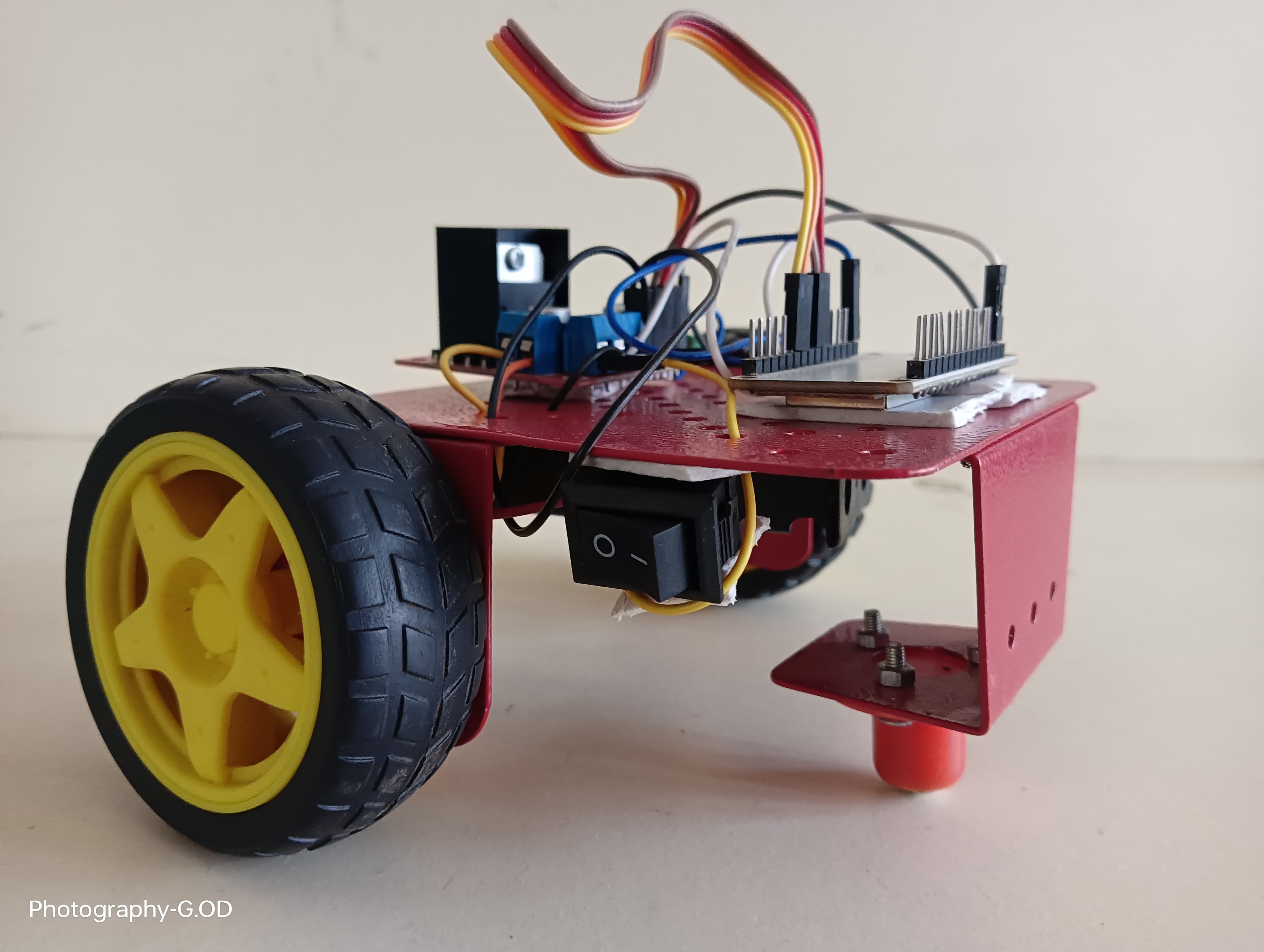
Project Overview
Remotely operated robot that can be controlled through WiFi, enabling long-distance manipulation.
Technical Analysis
Powered by NRC AIThis detailed technical analysis is designed for engineering students undertaking the "WiFi Control Bot" project. It covers the fundamental principles, practical implementation, and potential for advanced development.
WiFi Control Bot: Detailed Technical Analysis
article1. Technical Overview
The "WiFi Control Bot" is a remotely operated mobile robot that leverages WiFi connectivity for command and control. At its core, the project involves a microcontroller acting as a web server or a client communicating with a central server, processing commands received over a WiFi network, and translating them into motor actions.
Here's a breakdown of the technical flow:
- Microcontroller as the Brain: An ESP32 (or ESP8266) microcontroller serves as the robot's central processing unit. It's chosen specifically for its integrated WiFi capabilities, which eliminate the need for external WiFi modules.
- WiFi Connectivity: The ESP32 connects to an existing WiFi network (e.g., home router, mobile hotspot) as a station (client). Alternatively, it can act as an Access Point (AP), creating its own network that a control device (smartphone, computer) can connect to directly. For this project, we'll focus on the ESP32 as a station, acting as a web server.
- Web Server / Command Interface: The ESP32 hosts a simple web server. When a client device (e.g., a smartphone or computer with a web browser) connects to the ESP32's assigned IP address, the ESP32 serves a basic HTML page with control buttons (Forward, Backward, Left, Right, Stop).
- Command Transmission (HTTP GET): When a user clicks a button on the web interface, the browser sends an HTTP GET request to the ESP32's web server (e.g., ,
http://<ESP32_IP>/forward).http://<ESP32_IP>/stop - Command Reception and Parsing: The ESP32's web server continuously listens for incoming HTTP requests. Upon receiving a request, it parses the URL path (e.g., ,
/forward) to identify the desired command./stop - Motor Control Logic: Based on the received command, the ESP32 executes specific functions that manipulate its General Purpose Input/Output (GPIO) pins. These GPIO pins are connected to a motor driver module.
- Motor Driver (H-Bridge): The motor driver (e.g., L298N H-bridge) acts as an interface between the low-power signals from the ESP32's GPIOs and the higher-power requirements of the DC motors. It allows the ESP32 to control the direction and speed of the motors by switching voltages to them.
- Actuation: The motor driver provides the necessary current and voltage to power the DC gear motors, causing the robot to move according to the received commands.
- Power Management: A suitable power source (e.g., Li-ion battery pack) provides power to both the ESP32 and the motors, often requiring a voltage regulator to supply appropriate voltages to each component.
This architecture enables robust, long-distance control as long as both the robot and the control device are within range of the same WiFi network.
article2. Components Required
Here is a comprehensive list of components needed for the WiFi Control Bot project:
A. Electronic Components:
- Microcontroller:
- ESP32 Development Board (e.g., ESP32-WROOM-32 DevKitC): This is the brain of the robot, providing WiFi connectivity and processing power.
- Motor Driver:
- L298N Dual H-Bridge Motor Driver Module: Capable of driving two DC motors, providing sufficient current and voltage control. (Alternative: TB6612FNG for more efficiency and smaller size, but L298N is common for beginners).
- Motors:
- 2 x DC Gear Motors (100-300 RPM): Motors with reduction gears are preferred for robotics as they provide higher torque at lower speeds, suitable for robot movement. Look for "BO Motor" or "TT Motor" types.
- Power Supply:
- Li-ion Battery Pack (e.g., 2 x 18650 cells in series for ~7.4V, or 3 x 18650 for ~11.1V): Provides portable power for the robot. Ensure it can deliver sufficient current.
- 18650 Battery Holder (2 or 3 cell): To hold the batteries securely.
- DC-DC Buck Converter (e.g., LM2596 Module): To step down the battery voltage (e.g., 7.4V/11.1V) to 5V (for ESP32 VIN or USB power input) and/or to match motor driver input requirements. The ESP32 generally needs 5V or 3.3V, while L298N can handle 5-35V.
- Prototyping & Connectivity:
- Breadboard (Optional but recommended for prototyping): For easy temporary connections.
- Jumper Wires (Male-to-Male, Male-to-Female): Various lengths for making connections.
- USB Micro-B Cable (or USB-C depending on ESP32 board): For programming the ESP32 and initial power.
B. Mechanical Components & Materials:
- Robot Chassis:
- 2WD Robot Car Chassis Kit: Includes a base plate, motor mounts, and wheels. Simplifies mechanical assembly.
- Wheels:
- 2 x Robot Wheels (matching your motors): Usually come with the chassis kit or motor.
- 1 x Caster Wheel / Ball Caster: For stability and balance at the front or back of the 2-wheel drive robot.
- Mounting Hardware:
- Screws, Nuts, Standoffs: To mount components securely to the chassis.
- Adhesive:
- Double-sided Foam Tape or Hot Glue (Optional): For securing components like the battery holder if not using screws.
C. Tools (Not part of the bill of materials, but essential):
- Soldering Iron and Solder (if connecting components permanently)
- Wire Stripper/Cutter
- Small Screwdrivers (Philips and Flathead)
- Multimeter (for testing voltages and continuity)
- Computer with Arduino IDE installed
article3. Circuit Diagram Description
This section describes the wiring connections for the ESP32, L298N motor driver, DC motors, and power supply.
Assumptions for this diagram:
- Using an ESP32 DevKitC board.
- Using an L298N Dual H-Bridge Motor Driver module.
- Powering the system with a 2S (7.4V) or 3S (11.1V) Li-ion battery pack.
Power Supply Connections:
- Battery to Buck Converter Input:
- Connect the positive terminal of your Li-ion battery pack to the (or
VIN+) terminal of the LM2596 buck converter.IN+ - Connect the negative terminal of your Li-ion battery pack to the (or
VIN-) terminal of the LM2596 buck converter.IN-
- Connect the positive terminal of your Li-ion battery pack to the
- Buck Converter Output to L298N and ESP32:
- Motor Driver Power: The L298N requires a separate power input for the motors.
- Connect the positive output of the battery pack (or output of a buck converter regulated to motor voltage, if needed, though L298N can usually take battery voltage directly) to the (or
+12V/VCC_MOTOR) pin on the L298N module. If your motors are 6V, and battery is 11.1V, you might connect the buck output (regulated to 6V) here. If your battery is 7.4V and motors are 6V-12V, you can connect the 7.4V directly.VS - Connect the negative output of the battery pack (or GND from buck converter) to the pin on the L298N module.
GND
- Connect the positive output of the battery pack (or output of a buck converter regulated to motor voltage, if needed, though L298N can usually take battery voltage directly) to the
- ESP32 Power: The ESP32 typically requires 5V or 3.3V. It has an onboard regulator, so supplying 5V to the or
VINpin via the USB port is common.5V- Adjust the LM2596 buck converter's output to 5V DC.
- Connect the 5V output from the buck converter to the (or
VIN) pin on the ESP32 board.5V - Connect the GND output from the buck converter to any pin on the ESP32 board.
GND
- Motor Driver Power: The L298N requires a separate power input for the motors.
L298N Motor Driver and DC Motor Connections:
The L298N module has four output terminals (OUT1, OUT2, OUT3, OUT4) for two motors and several input pins for control (IN1, IN2, IN3, IN4, ENA, ENB).
- Motor 1 Connection:
- Connect one wire from DC Motor 1 to on the L298N.
OUT1 - Connect the other wire from DC Motor 1 to on the L298N.
OUT2
- Connect one wire from DC Motor 1 to
- Motor 2 Connection:
- Connect one wire from DC Motor 2 to on the L298N.
OUT3 - Connect the other wire from DC Motor 2 to on the L298N.
OUT4 - (Note: If a motor spins in the wrong direction, simply reverse its two wires connected to the L298N.)
- Connect one wire from DC Motor 2 to
ESP32 to L298N Control Connections (GPIO Pin Assignments):
We will use specific GPIO pins on the ESP32 to control the L298N. It's crucial to select pins that are not used for boot strapping or other internal functions during startup.
| L298N Pin | ESP32 GPIO Pin | Description |
|---|---|---|
| | Control pin for Motor 1 (Direction 1) |
| | Control pin for Motor 1 (Direction 2) |
| | Enable pin for Motor 1 (PWM capable for speed) |
| | Control pin for Motor 2 (Direction 1) |
| | Control pin for Motor 2 (Direction 2) |
| | Enable pin for Motor 2 (PWM capable for speed) |
| Any | Connect to ESP32 GND (Common Ground) |
| (Optional) | The L298N often has a 5V regulator. If using it, connect the 5V jumper. You might not need this if powering logic separately. Remove the jumper on L298N if supplying 5V externally to |
Important Notes:
- Common Ground: Ensure that the of the ESP32, the L298N, and the buck converter (and battery) are all connected together. This is fundamental for circuits to work correctly.
GND - PWM Pins: and
ENApins on the L298N can be connected to PWM-capable pins on the ESP32 (e.g., GPIO 25, 14 in our case) to control motor speed. If you don't need speed control, you can connectENBandENAdirectly toENB(or+5Vfrom ESP32 if stable) on the L298N module (usually by keeping the jumper on).3.3V - Jumper on L298N: The L298N module usually has a jumper near the pin to enable its onboard 5V regulator, which powers the logic part of the L298N. Keep this jumper in place if you are providing
+5V(motor power voltage) within the L298N's acceptable range (e.g., 7V-12V) and want the L298N to regulate its own 5V logic. If you are supplying 5V to the L298N'sVSpin from an external source (e.g., ESP32's 5V out or a separate 5V regulator), you must remove this jumper. For simplicity, keep the jumper and power+5Vdirectly from the battery.VS
Conceptual Wiring Diagram:
Li-ion Battery Pack (+ve) --- (GND) | | | | V V +---------------------+ | LM2596 Buck Converter| | IN+ IN- OUT+ OUT- | +---|---|-----|---|----+ | | | | | | | | (Adjust OUT to 5V) | | V V | +-----GND-+--------+ (Common Ground) | | | | | | +--------------------------------+-----------+----------+---------------------------------+ | | | | | +-----------------------------------------------------+ | | | ESP32 Dev Board | | | | VIN (5V) <-----(+5V from Buck) | | | | GND <-----(GND from Buck/Battery) | | | | | | | | GPIO 27 (IN1) ---------> L298N IN1 | | | | GPIO 26 (IN2) ---------> L298N IN2 | | | | GPIO 25 (ENA) ---------> L298N ENA | | | | GPIO 33 (IN3) ---------> L298N IN3 | | | | GPIO 32 (IN4) ---------> L298N IN4 | | | | GPIO 14 (ENB) ---------> L298N ENB | | | +-----------------------------------------------------+ | | | | | +-----------------------------------------------------------------------------------------+ | | | | V V Motor Driver L298N Module +-----------------------------------+ | IN1 IN2 ENA IN3 IN4 ENB | | | | | | | | | | +---+---+---+---+---+ | | | | OUT1 OUT2 OUT3 OUT4 | | | | | | | | | | | | | | V V V V | | Motor 1 Motor 2 | | | | VS (Motor Power) <----(+ve from Battery / Buck) | | GND <-----------------(GND from Battery / Buck) | +-----------------------------------+
article4. Source Code
This complete source code for the ESP32 implements the WiFi control bot with a simple web interface. It's written in Arduino (C++ for ESP32).
Programming Language: Arduino (C++)
C++#include <WiFi.h> #include <WebServer.h> #include <ESPmDNS.h> // For mDNS support (access by hostname like http://myrobot.local) // ----- WiFi Configuration ----- const char* ssid = "YOUR_WIFI_SSID"; // Your WiFi SSID const char* password = "YOUR_WIFI_PASSWORD"; // Your WiFi Password // ----- Motor Driver Pin Definitions (ESP32 GPIOs) ----- // Motor 1 (Left Motor) const int motor1_IN1 = 27; // ESP32 GPIO to L298N IN1 const int motor1_IN2 = 26; // ESP32 GPIO to L298N IN2 const int motor1_ENA = 25; // ESP32 GPIO to L298N ENA (PWM capable) // Motor 2 (Right Motor) const int motor2_IN3 = 33; // ESP32 GPIO to L298N IN3 const int motor2_IN4 = 32; // ESP32 GPIO to L298N IN4 const int motor2_ENB = 14; // ESP32 GPIO to L298N ENB (PWM capable) // ----- PWM Settings ----- const int freq = 30000; // PWM frequency (Hz) const int motor1_channel = 0; // PWM channel for Motor 1 ENA const int motor2_channel = 1; // PWM channel for Motor 2 ENB const int resolution = 8; // PWM resolution (8-bit = 0-255 duty cycle) int currentSpeed = 200; // Initial speed (0-255) // Create WebServer object on port 80 (standard HTTP port) WebServer server(80); // ----- Motor Control Functions ----- void setMotorSpeed(int motorChannel, int speed) { ledcWrite(motorChannel, speed); } void moveForward() { Serial.println("Moving Forward"); digitalWrite(motor1_IN1, HIGH); digitalWrite(motor1_IN2, LOW); digitalWrite(motor2_IN3, HIGH); digitalWrite(motor2_IN4, LOW); setMotorSpeed(motor1_channel, currentSpeed); setMotorSpeed(motor2_channel, currentSpeed); } void moveBackward() { Serial.println("Moving Backward"); digitalWrite(motor1_IN1, LOW); digitalWrite(motor1_IN2, HIGH); digitalWrite(motor2_IN3, LOW); digitalWrite(motor2_IN4, HIGH); setMotorSpeed(motor1_channel, currentSpeed); setMotorSpeed(motor2_channel, currentSpeed); } void turnLeft() { Serial.println("Turning Left (Left motor backward, Right motor forward)"); digitalWrite(motor1_IN1, LOW); // Left motor backward digitalWrite(motor1_IN2, HIGH); digitalWrite(motor2_IN3, HIGH); // Right motor forward digitalWrite(motor2_IN4, LOW); setMotorSpeed(motor1_channel, currentSpeed); setMotorSpeed(motor2_channel, currentSpeed); } void turnRight() { Serial.println("Turning Right (Left motor forward, Right motor backward)"); digitalWrite(motor1_IN1, HIGH); // Left motor forward digitalWrite(motor1_IN2, LOW); digitalWrite(motor2_IN3, LOW); // Right motor backward digitalWrite(motor2_IN4, HIGH); setMotorSpeed(motor1_channel, currentSpeed); setMotorSpeed(motor2_channel, currentSpeed); } void stopMotors() { Serial.println("Stopping Motors"); digitalWrite(motor1_IN1, LOW); digitalWrite(motor1_IN2, LOW); digitalWrite(motor2_IN3, LOW); digitalWrite(motor2_IN4, LOW); setMotorSpeed(motor1_channel, 0); // Set speed to 0 setMotorSpeed(motor2_channel, 0); // Set speed to 0 } // ----- Web Page Content ----- // HTML, CSS, and JavaScript for the control interface String sendHTML() { String ptr = "<!DOCTYPE html>"; ptr += "<html lang='en'>"; ptr += "<head>"; ptr += "<meta charset='UTF-8'>"; ptr += "<meta name='viewport' content='width=device-width, initial-scale=1.0'>"; ptr += "<title>WiFi Bot Control</title>"; ptr += "<style>"; ptr += "body { font-family: Arial, sans-serif; text-align: center; background-color: #f0f0f0; margin: 0; padding: 20px; }"; ptr += ".container { max-width: 400px; margin: 20px auto; background-color: #fff; padding: 20px; border-radius: 8px; box-shadow: 0 2px 4px rgba(0,0,0,0.1); }"; ptr += "h1 { color: #333; }"; ptr += ".controls { display: grid; grid-template-columns: repeat(3, 1fr); gap: 10px; margin-top: 20px; }"; ptr += ".button { padding: 15px 0; font-size: 1.2em; border: none; border-radius: 5px; cursor: pointer; transition: background-color 0.3s ease; text-decoration: none; color: white; display: flex; align-items: center; justify-content: center; }"; ptr += ".button:active { transform: translateY(1px); }"; // Simple active state ptr += ".forward { background-color: #4CAF50; grid-column: 2 / 3; }"; ptr += ".left { background-color: #f44336; }"; ptr += ".stop { background-color: #555; }"; ptr += ".right { background-color: #008CBA; }"; ptr += ".backward { background-color: #FFC107; grid-column: 2 / 3; }"; ptr += ".speed-control { margin-top: 20px; }"; ptr += ".speed-control input[type='range'] { width: 80%; }"; ptr += "</style>"; ptr += "</head>"; ptr += "<body>"; ptr += "<div class='container'>"; ptr += "<h1>WiFi Bot Control</h1>"; ptr += "<p>Use the buttons below to control the robot.</p>"; ptr += "<div class='controls'>"; ptr += "<a href='/forward' class='button forward'>FORWARD ▲</a>"; // Up Arrow ptr += "<a href='/left' class='button left'>LEFT ◀</a>"; // Left Arrow ptr += "<a href='/stop' class='button stop'>STOP ◼</a>"; // Square ptr += "<a href='/right' class='button right'>RIGHT ▶</a>"; // Right Arrow ptr += "<a href='/backward' class='button backward'>BACKWARD ▼</a>"; // Down Arrow ptr += "</div>"; ptr += "<div class='speed-control'>"; ptr += "<p>Speed: <span id='speedValue'>" + String(currentSpeed) + "</span></p>"; ptr += "<input type='range' min='0' max='255' value='" + String(currentSpeed) + "' id='speedRange'>"; ptr += "</div>"; ptr += "</div>"; ptr += "<script>"; ptr += "const speedRange = document.getElementById('speedRange');"; ptr += "const speedValue = document.getElementById('speedValue');"; ptr += "speedRange.oninput = function() {"; ptr += " speedValue.innerHTML = this.value;"; ptr += " fetch('/setSpeed?value=' + this.value);"; // Send speed value to ESP32 ptr += "};"; ptr += "</script>"; ptr += "</body>"; ptr += "</html>"; return ptr; } // ----- Web Server Request Handlers ----- void handleRoot() { server.send(200, "text/html", sendHTML()); } void handleForward() { moveForward(); server.sendHeader("Location", "/"); // Redirect back to root server.send(303); // See Other } void handleBackward() { moveBackward(); server.sendHeader("Location", "/"); server.send(303); } void handleLeft() { turnLeft(); server.sendHeader("Location", "/"); server.send(303); } void handleRight() { turnRight(); server.sendHeader("Location", "/"); server.send(303); } void handleStop() { stopMotors(); server.sendHeader("Location", "/"); server.send(303); } void handleSetSpeed() { if (server.hasArg("value")) { int newSpeed = server.arg("value").toInt(); if (newSpeed >= 0 && newSpeed <= 255) { currentSpeed = newSpeed; Serial.print("Speed set to: "); Serial.println(currentSpeed); // No need to update motors immediately, next movement command will use new speed } } server.send(200, "text/plain", "OK"); // Respond to AJAX request } void handleNotFound() { server.send(404, "text/plain", "Not Found"); } // ----- Setup Function ----- void setup() { Serial.begin(115200); // Configure motor control pins as OUTPUT pinMode(motor1_IN1, OUTPUT); pinMode(motor1_IN2, OUTPUT); pinMode(motor2_IN3, OUTPUT); pinMode(motor2_IN4, OUTPUT); // Configure PWM channels for motor enable pins ledcSetup(motor1_channel, freq, resolution); ledcAttachPin(motor1_ENA, motor1_channel); ledcSetup(motor2_channel, freq, resolution); ledcAttachPin(motor2_ENB, motor2_channel); stopMotors(); // Ensure motors are stopped at start // ----- WiFi Connection ----- Serial.print("Connecting to WiFi "); Serial.println(ssid); WiFi.begin(ssid, password); while (WiFi.status() != WL_CONNECTED) { delay(500); Serial.print("."); } Serial.println(""); Serial.println("WiFi connected."); Serial.print("IP Address: "); Serial.println(WiFi.localIP()); // ----- mDNS setup (Optional but Recommended) ----- if (!MDNS.begin("wifibot")) { // Access the bot using http://wifibot.local Serial.println("Error starting mDNS"); } else { Serial.println("mDNS responder started"); } // ----- Web Server Routing ----- server.on("/", handleRoot); server.on("/forward", HTTP_GET, handleForward); server.on("/backward", HTTP_GET, handleBackward); server.on("/left", HTTP_GET, handleLeft); server.on("/right", HTTP_GET, handleRight); server.on("/stop", HTTP_GET, handleStop); server.on("/setSpeed", HTTP_GET, handleSetSpeed); // New handler for speed control server.onNotFound(handleNotFound); server.begin(); // Start the web server Serial.println("HTTP server started."); } // ----- Loop Function ----- void loop() { server.handleClient(); // Handle incoming client requests MDNS.update(); // Keep mDNS responsive }
article5. Source Code Structure
The provided source code is structured to be modular and easy to understand for educational purposes.
A. Main Code Modules:
-
Configuration Module:
- ,
ssid: WiFi network credentials.password - ,
motor1_IN1,motor1_IN2,motor1_ENA,motor2_IN3,motor2_IN4: Pin definitions for connecting the ESP32 to the L298N motor driver.motor2_ENB - ,
freq,motor1_channel,motor2_channel,resolution: PWM parameters for motor speed control.currentSpeed
-
Motor Control Module:
- : A helper function to set the PWM duty cycle for a specific motor channel, controlling its speed.
setMotorSpeed(int motorChannel, int speed) - : Sets motor pins to drive both motors forward.
moveForward() - : Sets motor pins to drive both motors backward.
moveBackward() - : Sets motor pins to spin one motor forward and the other backward for turning.
turnLeft() - : Sets motor pins for the opposite turn.
turnRight() - : Sets all motor control pins to LOW and PWM to 0, stopping the robot.
stopMotors()
-
Web Interface Module (HTML/CSS/JavaScript):
- : A function that constructs the entire HTML page, including embedded CSS for styling and a small JavaScript snippet for dynamic speed control. This page is served to the client's web browser.
sendHTML()
-
Web Server Module:
- : Instantiates the web server object on port 80.
WebServer server(80) - : Handles requests to the root URL (
handleRoot()), sending the control HTML page./ - ,
handleForward(),handleBackward(),handleLeft(),handleRight(): Handlers for specific control URLs. They call the corresponding motor control functions and then redirect the browser back to the root page.handleStop() - : Handles AJAX requests from the web page's speed slider, updates
handleSetSpeed().currentSpeed - : Generic handler for any unrecognized URLs.
handleNotFound()
-
Setup and Loop Module:
- : The Arduino initialization function.
setup()- Initializes serial communication.
- Configures motor control pins as outputs.
- Sets up PWM channels for motor speed control.
- Connects to the WiFi network.
- Initializes mDNS (for friendly hostnames).
- Defines the URL routes and their respective handlers for the web server.
- Starts the web server.
- : The main loop function.
loop()- : Continuously checks for and processes incoming client requests to the web server. This is critical for the server to be responsive.
server.handleClient() - : Keeps the mDNS service running to resolve hostname requests.
MDNS.update()
B. Libraries Needed:
The project primarily uses standard libraries that come with the ESP32 Arduino core. You won't need to install them via the Library Manager unless your core installation is incomplete.
- : This library provides functionalities for connecting the ESP32 to a WiFi network (as a station or Access Point), managing WiFi settings, and getting network information (like IP address).
WiFi.h - : This library enables the ESP32 to act as a lightweight HTTP server, handling incoming web requests, defining routes, and sending responses (like HTML pages).
WebServer.h - : This library allows the ESP32 to register itself on the local network with a human-readable hostname (e.g.,
ESPmDNS.h), making it easier to access without knowing its IP address.wifibot.local
C. Key Functions:
- : Initiates the connection to a specified WiFi network.
WiFi.begin(ssid, password) - : Returns the current status of the WiFi connection (e.g.,
WiFi.status()).WL_CONNECTED - : Returns the IP address assigned to the ESP32 by the router.
WiFi.localIP() - : Configures a specified pin to behave as an input or an output.
pinMode(pin, mode) - : Writes a HIGH or LOW value to a digital pin.
digitalWrite(pin, value) - : Configures a PWM channel on the ESP32 with a given frequency and resolution.
ledcSetup(channel, freq, resolution) - : Attaches a GPIO pin to a configured PWM channel.
ledcAttachPin(pin, channel) - : Writes a duty cycle value (0-255 for 8-bit resolution) to a PWM channel, controlling the output voltage.
ledcWrite(channel, dutyCycle) - : Registers a function (
server.on(path, handlerFunction)) to be called when an HTTP GET request for a specifichandlerFunctionis received.path - : Starts the HTTP server, making it listen for incoming connections.
server.begin() - : This must be called repeatedly in the
server.handleClient()function to process pending client requests to the web server. Without it, the server will not respond.loop() - : Sends an HTTP response back to the client.
server.send(code, contentType, content) - : Initializes the mDNS service, allowing the device to be discoverable by its hostname.
MDNS.begin(hostname) - : Keeps the mDNS service active.
MDNS.update()
article6. Step-by-Step Implementation Guide
Follow these steps carefully to assemble your robot and program the ESP32.
label_importantA. Hardware Assembly Steps
-
Chassis Assembly:
- Unpack your 2WD robot chassis kit.
- Attach the DC gear motors to the motor mounts on the chassis plate using the provided screws.
- Mount the wheels onto the motor shafts. Ensure they are firmly pressed on.
- Attach the caster wheel to the front or back of the chassis.
- Ensure all motor wires are free to move and not tangled.
-
Power System Setup:
- Mount the 18650 battery holder to the chassis using screws or strong double-sided tape. Insert your charged batteries.
- Mount the LM2596 buck converter module.
- Wire Battery to Buck Converter: Connect the positive () and negative (
+) terminals of the battery holder to the-andIN+terminals of the LM2596 buck converter, respectively.IN- - Adjust Buck Converter Output: Connect your multimeter to the and
OUT+terminals of the buck converter. Carefully turn the small potentiometer screw on the buck converter until the output voltage reads exactly 5V DC. Do this before connecting anything else to the output!OUT-
-
Motor Driver (L298N) Mounting & Wiring:
- Mount the L298N module to the chassis.
- Power L298N:
- Connect the positive output of your battery pack (e.g., 7.4V or 11.1V) directly to the (or
+12V) terminal on the L298N module.VS - Connect the negative terminal of your battery pack (GND) to the terminal on the L298N module.
GND - Ensure the 5V jumper on the L298N module is in place if you want to use its internal 5V regulator for its logic.
- Connect the positive output of your battery pack (e.g., 7.4V or 11.1V) directly to the
- Connect Motors to L298N:
- Connect the two wires from Motor 1 (Left) to and
OUT1on the L298N.OUT2 - Connect the two wires from Motor 2 (Right) to and
OUT3on the L298N.OUT4
- Connect the two wires from Motor 1 (Left) to
-
ESP32 Mounting & Wiring:
- Mount the ESP32 DevKitC board to the chassis.
- Power ESP32:
- Connect the 5V output from the LM2596 buck converter to the (or
VIN) pin on the ESP32 board.5V - Connect the output from the LM2596 buck converter to any
GNDpin on the ESP32 board.GND
- Connect the 5V output from the LM2596 buck converter to the
- Connect ESP32 to L298N Control Pins:
- ESP32 to L298N
GPIO 27IN1 - ESP32 to L298N
GPIO 26IN2 - ESP32 to L298N
GPIO 25ENA - ESP32 to L298N
GPIO 33IN3 - ESP32 to L298N
GPIO 32IN4 - ESP32 to L298N
GPIO 14ENB - Connect one of the pins on the ESP32 to the
GNDpin on the L298N (ensuring common ground).GND
- ESP32
-
Final Checks:
- Double-check all wiring connections for correctness and polarity. Incorrect wiring can damage components.
- Ensure no wires are loose or can short circuit.
label_importantB. Software Setup and Programming
-
Install Arduino IDE:
- Download and install the latest Arduino IDE from arduino.cc.
-
Install ESP32 Board Manager:
- Open Arduino IDE.
- Go to .
File > Preferences - In the "Additional Boards Manager URLs" field, add:
https://raw.githubusercontent.com/espressif/arduino-esp32/gh-pages/package_esp32_index.json - Click .
OK - Go to .
Tools > Board > Boards Manager... - Search for "ESP32" and install the "esp32 by Espressif Systems" package.
-
Select Board and Port:
- Go to and select your specific ESP32 board (e.g., "ESP32 Dev Module" or "ESP32 Wrover Module").
Tools > Board > ESP32 Arduino - Connect your ESP32 board to your computer using a USB cable.
- Go to and select the COM port corresponding to your ESP32.
Tools > Port
- Go to
-
Copy and Customize Code:
- Copy the provided source code into a new Arduino sketch.
- IMPORTANT: Update the and
ssidvariables with your actual WiFi network credentials.passwordC++const char* ssid = "YOUR_WIFI_SSID"; // Your WiFi SSID const char* password = "YOUR_WIFI_PASSWORD"; // Your WiFi Password - Review the pin assignments (, etc.) to ensure they match your physical connections. If you used different GPIOs, update the code accordingly.
motor1_IN1
-
Verify and Upload:
- Click the "Verify" (checkmark) button to compile the code and check for errors.
- Once compiled successfully, click the "Upload" (right arrow) button to flash the code to your ESP32.
- Troubleshooting Upload: If you have issues, try holding down the "BOOT" button on your ESP32 board while pressing "Upload" in the IDE, then release "BOOT" once the upload starts.
label_importantC. Testing and Calibration Procedures
-
Serial Monitor for WiFi Status:
- After uploading, open the Serial Monitor ().
Tools > Serial Monitor - Set the baud rate to .
115200 - You should see the ESP32 attempting to connect to your WiFi network. Once connected, it will print its assigned IP address (e.g., ).
IP Address: 192.168.1.100 - Also, note the mDNS hostname (e.g., ).
wifibot.local
- After uploading, open the Serial Monitor (
-
Access Web Interface:
- On a device (smartphone, computer) connected to the same WiFi network as your ESP32, open a web browser.
- Enter the IP address shown in the Serial Monitor (e.g., ) or the mDNS hostname (
192.168.1.100).http://wifibot.local - You should see the "WiFi Bot Control" web page with the control buttons.
-
Test Motor Movements:
- Place the robot on a flat surface where it can move freely.
- Click the "FORWARD" button. The robot should move forward.
- Click "STOP". The robot should stop.
- Click "BACKWARD", "LEFT", "RIGHT", and observe the robot's movement.
- Test the speed slider to see if the robot's speed changes.
-
Calibrate Motor Directions:
- If the robot moves backward when you click "FORWARD", or turns right when you click "LEFT", you need to calibrate.
- Method 1 (Hardware): Swap the two wires of the problematic motor connected to the L298N module (e.g., swap OUT1 and OUT2 for Motor 1).
- Method 2 (Software): In the code, for the problematic motor, swap and
HIGHfor itsLOWpins in the respectiveIN,moveForward(),moveBackward(),turnLeft()functions. For example, ifturnRight()wasmotor1_IN1for forward, make itHIGHandLOWmotor1_IN2. Re-upload the code after changes.HIGH - After adjustment, retest all directions.
-
Range Testing:
- Test the robot's responsiveness at various distances from your WiFi router or access point. Note any areas where the connection becomes unreliable.
article7. Challenges and Solutions
Students commonly encounter several challenges during this project. Here are some of them and their solutions:
-
Challenge: ESP32 Not Connecting to WiFi.
- Symptoms: Serial Monitor repeatedly prints "...", "Connecting to WiFi...", or "WiFi failed to connect".
- Solutions:
- Incorrect SSID/Password: Double-check the and
ssidvariables in your code. They are case-sensitive. There should be no extra spaces.password - Out of Range/Weak Signal: Move the ESP32 closer to your WiFi router.
- Network Type: ESP32 mostly supports 2.4GHz WiFi. Ensure your router is broadcasting on 2.4GHz.
- Firewall/Router Settings: Some public or university networks might block new devices or port 80. Try using a personal hotspot from your phone or a private home network.
- Incorrect Board/Port: Ensure you've selected the correct ESP32 board and COM port in the Arduino IDE menu.
Tools
- Incorrect SSID/Password: Double-check the
-
Challenge: Motors Not Moving or Moving Erratically.
- Symptoms: Motors make no sound, spin weakly, spin in the wrong direction, or only one motor spins.
- Solutions:
- Wiring Errors: Re-check all wiring connections:
- L298N Power: Ensure and
VSon L298N are correctly connected to the battery/power supply.GND - Motor Connections: Ensure motors are connected to and
OUT1/OUT2.OUT3/OUT4 - Control Pin Connections: Verify ESP32 GPIOs are correctly connected to L298N and
INpins.EN - Common Ground: Crucially, ensure all pins (ESP32, L298N, Battery, Buck Converter) are connected together.
GND
- L298N Power: Ensure
- Insufficient Power:
- Battery Voltage: Check battery voltage under load. If it drops too low, the motors won't get enough power. Use fresh, charged batteries.
- Current Capacity: Ensure your battery can supply enough current. Motors can draw significant current, especially during start-up.
- L298N Jumper: Make sure the 5V jumper on the L298N module is in place if you're relying on its internal 5V regulator for its logic. If you are supplying external 5V to the L298N 5V pin, remove this jumper.
- PWM Issues: If motors are weak, ensure /
ENApins are connected to PWM-capable pins on ESP32 andENBis correctly setting the speed.ledcWrite - Motor Direction: If a motor spins the wrong way, swap its two wires at the L298N output.
- Wiring Errors: Re-check all wiring connections:
-
Challenge: Web Page Not Loading / "Page Not Found".
- Symptoms: Browser shows "This site can't be reached", "ERR_CONNECTION_REFUSED", or "404 Not Found".
- Solutions:
- Incorrect IP Address: Verify the ESP32's IP address from the Serial Monitor. Double-check you're typing it correctly into the browser.
- WiFi Connection: Ensure the ESP32 is successfully connected to WiFi (check Serial Monitor).
- Client on Same Network: Make sure the device you're using to control the bot is connected to the same WiFi network as the ESP32.
- in
server.handleClient(): Confirmloop()is present and correctly called in yourserver.handleClient();function. Without it, the server won't process requests.loop() - Router Blocking Port 80: Less common on home networks, but some routers might block default HTTP port 80.
- mDNS Failure: If using and it fails, try the IP address directly. Ensure
wifibot.localandMDNS.begin("wifibot")are in the code.MDNS.update()
-
Challenge: ESP32 Resets or Freezes Randomly.
- Symptoms: ESP32 restarts, drops WiFi connection, or becomes unresponsive.
- Solutions:
- Power Supply Issues: This is a very common problem. The ESP32 can draw significant current, especially when WiFi is active.
- Voltage Drops (Brownouts): Ensure your 5V power supply to the ESP32 is stable and can provide sufficient current (at least 500mA, preferably 1A or more for stability). The LM2596 buck converter should be robust enough.
- Motor Current Spikes: When motors start or change direction, they draw large current spikes. If the motor power supply (battery) also powers the ESP32 without proper isolation/regulation, these spikes can cause voltage dips that reset the ESP32. Ensure separate voltage regulation for the ESP32 (e.g., the 5V buck converter).
- Capacitors: Adding a large electrolytic capacitor (e.g., 470uF or 1000uF) across the ESP32's 5V and GND pins can help stabilize the power supply during current spikes.
- Code Issues: Infinite loops or excessive delays in can prevent
loop()from running, making the board seem frozen. Avoidserver.handleClient()for long periods; usedelay()for non-blocking delays.millis()
- Power Supply Issues: This is a very common problem. The ESP32 can draw significant current, especially when WiFi is active.
-
Challenge: Code Upload Fails.
- Symptoms: "A fatal error occurred: Failed to connect to ESP32: Timed out waiting for packet header".
- Solutions:
- Wrong Port/Board: Double-check and
Tools > Port.Tools > Board - Drivers: Ensure USB-to-serial drivers are installed for your ESP32 board's chip (e.g., CP210x or CH340).
- Boot Mode: For many ESP32 boards, you need to hold the "BOOT" button (sometimes labeled "FLASH") while clicking "Upload" in the IDE, then release it once "Connecting..." appears.
- Faulty USB Cable: Try a different USB cable, some are only for charging and lack data lines.
- Wrong Port/Board: Double-check
article8. Learning Outcomes
This project offers a rich learning experience for engineering students, covering multiple disciplines within electronics, programming, and robotics:
-
Microcontroller Programming (ESP32/Arduino IDE):
- Gaining proficiency in writing C++ code within the Arduino framework.
- Understanding and
setup()functions.loop() - Using digital I/O for basic control (,
pinMode).digitalWrite - Implementing Pulse Width Modulation (PWM) for analog control (motor speed) using ,
ledcSetup,ledcAttachPin.ledcWrite
-
Wireless Communication (WiFi):
- Understanding client-server architecture over WiFi.
- Connecting a microcontroller to a WiFi network (Station mode).
- Implementing a basic HTTP web server on an embedded device.
- Handling HTTP GET requests and serving web pages.
- Understanding IP addresses, ports, and mDNS for network discovery.
-
Motor Control Fundamentals:
- Learning about DC motors and their operation.
- Understanding the need for motor drivers (H-bridges) to interface between microcontrollers and high-current motors.
- Controlling motor direction and speed using logic pins and PWM.
- Practical experience with the L298N motor driver.
-
Basic Web Development:
- Creating simple HTML for a user interface.
- Applying basic CSS for styling.
- Implementing rudimentary JavaScript for interactive elements (like the speed slider).
- Understanding how a browser interacts with a web server to send commands.
-
Power Management:
- Understanding the importance of appropriate power sources for different components (microcontroller vs. motors).
- Practical experience with voltage regulators (buck converters) for stepping down voltage.
- Addressing common power-related issues like brownouts and current spikes.
-
System Integration and Troubleshooting:
- Connecting various electronic and mechanical components to form a functional system.
- Developing systematic debugging and troubleshooting skills for both hardware and software issues (e.g., using Serial Monitor, multimeter).
- Identifying and resolving common problems like wiring errors, power issues, and communication failures.
-
Robotics Concepts:
- Introduction to mobile robotics (2-wheel drive kinematics).
- Grasping the concept of remote control in robotics.
-
Project Management:
- Breaking down a complex project into manageable steps.
- Planning components, wiring, and code structure.
- Testing and iterating on designs.
article9. Extensions and Improvements
This project serves as an excellent foundation for numerous extensions and improvements, pushing students to explore more advanced robotics and IoT concepts.
-
Advanced Control Interface:
- Joystick Control: Implement a more intuitive control using a virtual joystick on the web interface (via JavaScript) or physical joystick connected to an input module (e.g., PS2 controller via Bluetooth, or analog joystick module connected to ESP32 ADC pins).
- WebSockets for Real-time Control: Instead of HTTP GET requests, use WebSockets for continuous, low-latency, real-time control. This is more suitable for dynamic movements and avoids constant page reloads.
- Dedicated Mobile App: Develop a simple Android or iOS application for a more refined user experience and better integration with mobile device features (e.g., accelerometer for tilt control).
-
Sensors Integration for Autonomy/Feedback:
- Obstacle Avoidance: Add an Ultrasonic Sensor (HC-SR04) to detect obstacles. Implement simple logic to stop or navigate around them.
- Line Following: Integrate IR line follower sensors to enable the robot to follow a black line on a white surface.
- Odometry/Feedback: Attach Rotary Encoders to the motors to measure wheel rotation. This allows for more precise movement (e.g., move exactly 1 meter, turn exactly 90 degrees) and feedback on actual speed.
- Battery Monitoring: Use a voltage divider and ADC pin to monitor the battery voltage and display it on the web interface.
-
Enhanced Mobility & Actuators:
- Servos: Add a servo motor to control a pan/tilt mechanism for a sensor (e.g., ultrasonic or camera) or a small robotic arm.
- Omni-directional Wheels: Explore omni-directional or mecanum wheels for more complex movement patterns.
-
Communication Protocols:
- MQTT (Message Queuing Telemetry Transport): Implement MQTT for communication. This is ideal for IoT applications, allowing the robot to connect to a broker and subscribe/publish topics for commands and sensor data.
- Bluetooth Low Energy (BLE): Utilize ESP32's BLE capability for shorter-range, lower-power direct control from a smartphone without a WiFi router.
-
Camera & Video Streaming:
- Integrate an ESP32-CAM module or a small USB camera. Stream live video from the robot to the control interface, providing a "first-person view" (FPV) experience. This significantly enhances remote operation.
-
Advanced Programming & Logic:
- PID Control: Implement PID (Proportional-Integral-Derivative) control for precise motor speed regulation, ensuring both wheels spin at the desired speed and handling varying loads.
- State Machine: Design a state machine for complex robot behaviors (e.g., idle, moving, avoiding obstacle, charging).
- Over-the-Air (OTA) Updates: Enable wireless firmware updates for the ESP32, allowing you to update the code without physically connecting the USB cable.
-
Power System Optimization:
- Battery Management System (BMS): Integrate a small BMS for safer charging and discharging of Li-ion batteries.
- Solar Charging: Add a small solar panel and charge controller for continuous operation in outdoor environments.
-
Physical Design & Aesthetics:
- 3D Printing: Design and 3D-print custom parts for the chassis, sensor mounts, or enclosures.
- Lighting/Indicators: Add LEDs for status indicators (e.g., WiFi connected, moving, battery low) or headlights/taillights.
By pursuing these extensions, students can delve deeper into specific areas of robotics, IoT, and embedded systems, transforming a simple remote control bot into a more intelligent and capable autonomous platform.
infoThis analysis is generated by AI and should be used as a learning guide. Always verify technical details.