


Climbing Robot
Climbing Robot is an autonomous engineering project developed by the NIST Robotics Club (NRC) at NIST University, Berhampur. A specialized robot designed to climb vertical surfaces using advanced grip mechanisms and balance systems.

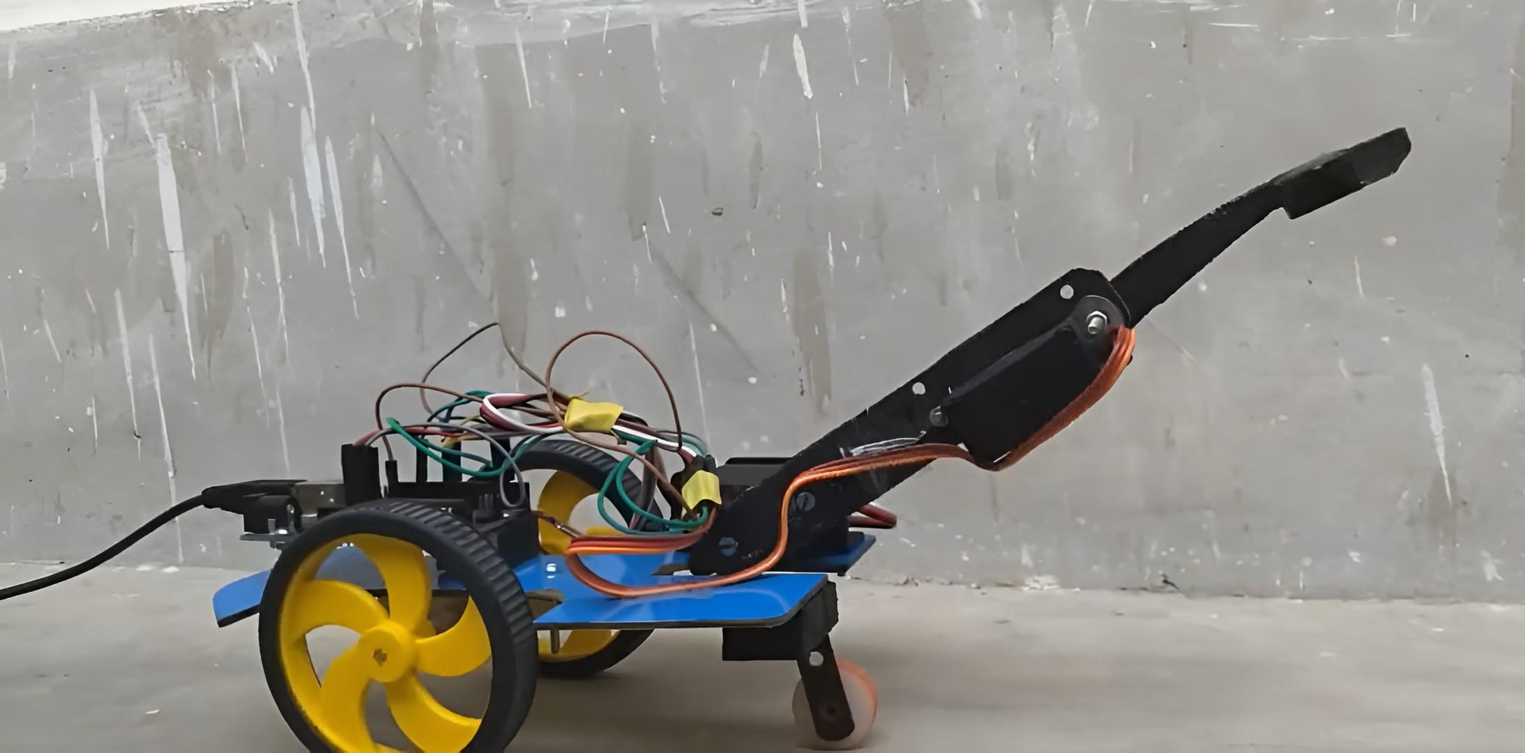
Project Overview
A specialized robot designed to climb vertical surfaces using advanced grip mechanisms and balance systems.
Technical Analysis
Powered by NRC AIAs a robotics and electronics expert, I'm excited to provide a comprehensive technical analysis for your "Climbing Robot" project. This project is excellent for engineering students as it integrates mechanical design, electronics, sensor integration, and control systems.
articleDetailed Technical Analysis: Climbing Robot
Project Description: A specialized robot designed to climb vertical surfaces using advanced grip mechanisms and balance systems.
label_important1. Technical Overview
The climbing robot's primary function is to move vertically on smooth surfaces. This typically involves a locomotion strategy and a robust grip mechanism, complemented by a stability system and a central control unit.
a. Grip Mechanism (Focus: Vacuum Suction Cups) For smooth surfaces like glass, painted walls, or polished metal, vacuum suction cups are a common and effective choice.
- Principle: A vacuum pump or motor creates a negative pressure inside a sealed cup, causing it to adhere strongly to the surface due due to atmospheric pressure.
- Actuation: Small DC vacuum pumps are used to create the suction. For releasing, either the pump is turned off and a bleed valve is opened, or the cups are designed to deform slightly to break the seal. For an inchworm robot, two sets of suction cups (front and rear) are needed, each controlled independently.
b. Locomotion Strategy (Focus: Inchworm/Caterpillar Movement) This strategy is highly effective for climbing with distinct front and rear grip points.
- Two Segments: The robot is conceptually divided into a "front" and a "rear" segment, connected by an extendable/contractible mechanism (e.g., a linear actuator, or a pair of motors driving a rack-and-pinion/lead screw).
- Movement Cycle (4-Phase):
- Phase 1: Front Grip, Rear Release: The front segment's suction cups activate, adhering to the wall. The rear segment's suction cups deactivate, releasing from the wall.
- Phase 2: Rear Advance: The connection mechanism extends, pulling the released rear segment upwards towards the front segment.
- Phase 3: Rear Grip, Front Release: The rear segment's suction cups activate, adhering to the wall. The front segment's suction cups deactivate, releasing.
- Phase 4: Front Advance: The connection mechanism retracts, pulling the released front segment upwards towards the newly gripped rear segment.
- This cycle repeats, allowing the robot to "inch" its way up the vertical surface.
c. Balance and Stability System Maintaining balance is critical to prevent the robot from peeling off the wall, especially during transitions or if the surface isn't perfectly vertical.
- Sensors: An Inertial Measurement Unit (IMU), typically comprising an accelerometer and a gyroscope (e.g., MPU6050), is used to measure the robot's pitch (tilt forward/backward) and roll (tilt side-to-side) angles relative to gravity.
- Control Loop: The microcontroller reads the IMU data. If the robot starts to tilt excessively, the control system can:
- Adjust the speed or direction of the locomotion motors to compensate.
- Potentially adjust the suction pressure (if controllable) or re-grip.
- Slow down or pause movement until stability is re-established.
d. Central Control Unit
- Microcontroller: An Arduino (e.g., Uno, Mega) or ESP32 serves as the brain, processing sensor data, executing the locomotion algorithm, and controlling actuators.
- Motor Drivers: H-bridge motor drivers (e.g., L298N, DRV8825) are used to control the speed and direction of the DC motors for locomotion and the vacuum pump.
- Power Management: A suitable battery pack (e.g., LiPo) provides power, and buck converters regulate voltage for the microcontroller and sensors.
label_important2. Components Required
Here's a detailed list of components for a suction-cup based inchworm climbing robot:
a. Electronic Components:
- Microcontroller Board: Arduino Uno R3 (or Arduino Mega 2560 for more I/O pins and memory).
- Motor Driver: L298N Dual H-Bridge Motor Driver Module (at least 2 modules, one for locomotion motors, one for vacuum pump and potentially a linear actuator).
- Vacuum Pumps: 2 x Small DC Vacuum Air Pumps (e.g., 370 motor type, 3-6V or 6-12V, depending on chosen model and power supply).
- DC Motors (for Locomotion): 2 x Geared DC Motors (e.g., N20 gear motors, 6V or 12V, appropriate RPM for controlled movement) or a linear actuator (e.g., mini servo linear actuator, or a DC motor with lead screw). For simplicity, we'll assume two standard DC motors connected to a rack-and-pinion or similar mechanism for linear movement.
- IMU Sensor: MPU6050 Accelerometer Gyroscope Module (I2C interface).
- Power Supply:
- 1 x LiPo Battery (e.g., 2S 7.4V or 3S 11.1V, 1500mAh - 3000mAh, choose based on motor voltage).
- 1 x DC-DC Buck Converter Module (LM2596 or similar, to step down battery voltage to 5V for Arduino/MPU6050).
- Connectors & Wires: Jumper wires (male-to-male, male-to-female), power connectors (XT60/JST).
- Breadboard (optional): For prototyping small circuits.
- Resistors & Capacitors (optional but good practice): For pull-ups/downs or smoothing.
- LEDs: For status indication/debugging.
- SPDT Switch: For power ON/OFF.
b. Mechanical Components & Materials:
- Suction Cups: 2 pairs of high-quality flexible rubber/silicone suction cups (e.g., 40-60mm diameter), designed for vacuum. Ensure they have good sealing properties.
- Frame Material: Lightweight yet rigid material such as:
- Acrylic sheets (3-5mm thickness)
- Thin aluminum sheets or profiles
- 3D-printed parts (PLA, PETG, ABS)
- Linear Motion Mechanism:
- Option 1 (Simpler): Two DC motors with wheels/tracks, moving on a smooth track or rail that connects the front and rear segments. This allows the body to extend/retract.
- Option 2 (More direct): A rack-and-pinion system driven by a DC motor, or a lead screw system driven by a DC motor, to extend and retract the robot body.
- Fasteners: Small screws, nuts, standoffs, zip ties.
- Tubing: Flexible silicone tubing for connecting vacuum pumps to suction cups.
label_important3. Circuit Diagram Description
This description assumes an Arduino Uno, L298N drivers, MPU6050, two DC motors for locomotion (front/rear drive), and two separate vacuum pumps (front/rear suction).
a. Power Distribution:
- LiPo Battery (e.g., 7.4V): Connect to the (or
+12V) terminal of both L298N modules. Also connect to the input of the DC-DC Buck Converter.VMS - DC-DC Buck Converter:
- Input: Connect to LiPo Battery output.
- Output: Set to 5V.
- Connect the 5V output to:
- Arduino Uno pin.
5V - MPU6050 pin.
VCC - logic input of L298N modules (via the
5Vpin, usually next to5Vfor the logic part).GND
- Arduino Uno
- Ground (GND): All GNDs must be common: LiPo , Arduino
GND, L298NGND(power and logic), MPU6050GND, DC-DC Buck ConverterGND.GND
b. Arduino Uno Connections:
-
Motor Driver 1 (L298N for Locomotion)
- (Enable for Motor A): Connect to Arduino Digital Pin 9 (PWM).
ENA - (Motor A Input 1): Connect to Arduino Digital Pin 8.
IN1 - (Motor A Input 2): Connect to Arduino Digital Pin 7.
IN2 - (Enable for Motor B): Connect to Arduino Digital Pin 11 (PWM).
ENB - (Motor B Input 1): Connect to Arduino Digital Pin 10.
IN3 - (Motor B Input 2): Connect to Arduino Digital Pin 12.
IN4 - ,
OUT1: Connect to Locomotion Motor 1.OUT2 - ,
OUT3: Connect to Locomotion Motor 2.OUT4 - (or
+12V): Connect to LiPo Battery positive.VMS - : Connect to common GND.
GND - (Logic): Connect to 5V output of Buck Converter.
5V
-
Motor Driver 2 (L298N for Vacuum Pumps)
- (Enable for Pump Front): Connect to Arduino Digital Pin 5 (PWM).
ENA - (Pump Front Input 1): Connect to Arduino Digital Pin 4.
IN1 - (Pump Front Input 2): Connect to Arduino Digital Pin 3. (Note: For a simple DC pump, only one input might be needed if direction doesn't matter, or control via ENA/ENB directly, but L298N expects two inputs for on/off).
IN2 - (Enable for Pump Rear): Connect to Arduino Digital Pin 6 (PWM).
ENB - (Pump Rear Input 1): Connect to Arduino Digital Pin 2.
IN3 - (Pump Rear Input 2): Connect to Arduino Digital Pin 1. (Digital Pin 0/1 are RX/TX, best to avoid if using Serial Monitor. Use other available pins if possible, e.g., A0-A3 as digital, or pins 13). Let's adjust to be safer:
IN4- Pump Front: ENA (Pin 5), IN1 (Pin 4), IN2 (Pin 3)
- Pump Rear: ENB (Pin 6), IN3 (Pin A0), IN4 (Pin A1) - Using Analog pins as Digital
- ,
OUT1: Connect to Front Vacuum Pump.OUT2 - ,
OUT3: Connect to Rear Vacuum Pump.OUT4 - (or
+12V): Connect to LiPo Battery positive.VMS - : Connect to common GND.
GND - (Logic): Connect to 5V output of Buck Converter.
5V
-
MPU6050 IMU Sensor:
- : Connect to 5V output of Buck Converter.
VCC - : Connect to common GND.
GND - (Serial Clock): Connect to Arduino Analog Pin A5 (I2C Clock).
SCL - (Serial Data): Connect to Arduino Analog Pin A4 (I2C Data).
SDA - (Address Select): Leave unconnected or connect to GND (selects I2C address 0x68). If connected to VCC, address is 0x69.
AD0
c. Vacuum Pump/Solenoid Valve Control Notes:
- If using simple DC vacuum pumps, one motor driver channel (two outputs) per pump. The pins set direction (which is irrelevant for a pump, so one
INpin to HIGH and the other to LOW, then control withIN/ENAfor PWM speed, orENBpins directly for ON/OFF).IN - If using solenoid valves to control vacuum to separate cups from a single pump, a MOSFET or relay module might be better for valve control than L298N, unless the valves draw minimal current. Each valve would need a dedicated control pin. For this example, we assume two pumps for simplicity.
label_important4. Source Code (Arduino C++)
This code provides a basic framework for an inchworm climbing robot using two locomotion motors, two vacuum pumps, and MPU6050 for balance.
C++#include <Wire.h> #include <Adafruit_MPU6050.h> // You might need to install this library via Arduino IDE Library Manager #include <Adafruit_Sensor.h> // --- Pin Definitions --- // Locomotion Motors (using L298N 1) #define MOTOR_L_EN 9 // Left Motor Enable (PWM) #define MOTOR_L_IN1 8 // Left Motor Input 1 #define MOTOR_L_IN2 7 // Left Motor Input 2 #define MOTOR_R_EN 11 // Right Motor Enable (PWM) #define MOTOR_R_IN1 10 // Right Motor Input 1 #define MOTOR_R_IN2 12 // Right Motor Input 2 // Vacuum Pumps (using L298N 2) #define PUMP_FRONT_EN 5 // Front Pump Enable (PWM) #define PUMP_FRONT_IN1 4 // Front Pump Input 1 #define PUMP_FRONT_IN2 3 // Front Pump Input 2 #define PUMP_REAR_EN 6 // Rear Pump Enable (PWM) #define PUMP_REAR_IN1 A0 // Rear Pump Input 1 (Analog pin used as digital) #define PUMP_REAR_IN2 A1 // Rear Pump Input 2 (Analog pin used as digital) // --- MPU6050 Sensor --- Adafruit_MPU6050 mpu; // --- Robot State Variables --- enum RobotState { STATE_INIT, STATE_GRIP_FRONT, STATE_RELEASE_REAR, STATE_ADVANCE_REAR, STATE_GRIP_REAR, STATE_RELEASE_FRONT, STATE_ADVANCE_FRONT, STATE_HOLD_POSITION, // New state for holding and balance correction STATE_ERROR }; RobotState currentState = STATE_INIT; unsigned long stateStartTime = 0; // To track time spent in a state unsigned long stepDuration = 3000; // Time for each major step (e.g., 3 seconds) unsigned long pumpActivationTime = 1500; // Time for pump to build sufficient vacuum int motorSpeed = 150; // PWM speed for locomotion (0-255) int pumpSpeed = 200; // PWM speed for pumps // --- Balance Control Variables --- float desiredPitch = 0.0; // Desired pitch angle (robot perfectly vertical) float pitchTolerance = 5.0; // Max allowed deviation in degrees float Kp_pitch = 5.0; // Proportional gain for pitch control (adjust this!) // --- Functions for Actuator Control --- void setLocomotionMotors(int leftSpeed, int rightSpeed) { // Left Motor if (leftSpeed > 0) { digitalWrite(MOTOR_L_IN1, HIGH); digitalWrite(MOTOR_L_IN2, LOW); } else if (leftSpeed < 0) { digitalWrite(MOTOR_L_IN1, LOW); digitalWrite(MOTOR_L_IN2, HIGH); leftSpeed = abs(leftSpeed); } else { digitalWrite(MOTOR_L_IN1, LOW); digitalWrite(MOTOR_L_IN2, LOW); } analogWrite(MOTOR_L_EN, leftSpeed); // Right Motor if (rightSpeed > 0) { digitalWrite(MOTOR_R_IN1, HIGH); digitalWrite(MOTOR_R_IN2, LOW); } else if (rightSpeed < 0) { digitalWrite(MOTOR_R_IN1, LOW); digitalWrite(MOTOR_R_IN2, HIGH); rightSpeed = abs(rightSpeed); } else { digitalWrite(MOTOR_R_IN1, LOW); digitalWrite(MOTOR_R_IN2, LOW); } analogWrite(MOTOR_R_EN, rightSpeed); Serial.print("Motors: L="); Serial.print(leftSpeed); Serial.print(", R="); Serial.println(rightSpeed); } void setFrontPump(bool activate) { if (activate) { digitalWrite(PUMP_FRONT_IN1, HIGH); digitalWrite(PUMP_FRONT_IN2, LOW); analogWrite(PUMP_FRONT_EN, pumpSpeed); Serial.println("Front Pump Activated"); } else { digitalWrite(PUMP_FRONT_IN1, LOW); digitalWrite(PUMP_FRONT_IN2, LOW); analogWrite(PUMP_FRONT_EN, 0); // Turn off PWM Serial.println("Front Pump Deactivated"); } } void setRearPump(bool activate) { if (activate) { digitalWrite(PUMP_REAR_IN1, HIGH); digitalWrite(PUMP_REAR_IN2, LOW); analogWrite(PUMP_REAR_EN, pumpSpeed); Serial.println("Rear Pump Activated"); } else { digitalWrite(PUMP_REAR_IN1, LOW); digitalWrite(PUMP_REAR_IN2, LOW); analogWrite(PUMP_REAR_EN, 0); // Turn off PWM Serial.println("Rear Pump Deactivated"); } } // --- IMU Reading Function --- float readPitch() { sensors_event_t a, g, temp; mpu.getEvent(&a, &g, &temp); // Simple pitch calculation from accelerometer (roll is often less critical for 2D climbing) // This assumes the robot is climbing vertically, and X-axis is perpendicular to gravity when flat. // When climbing, the Y-axis would be aligned with gravity if perfectly vertical. // Pitch (rotation around X-axis) = atan2(accel.y, sqrt(accel.x^2 + accel.z^2)) * 180 / PI; // This value will be 0 when horizontal, and 90 when perfectly vertical. // We want to calculate deviation from 90 degrees if climbing upwards. // So, if robot's Y-axis is pointing up the wall, and Z is away from wall: // Pitch = atan2(a.acceleration.z, a.acceleration.y) * 180.0 / PI; // This might need calibration based on how you mount the MPU6050. // For a robot climbing vertically, with its 'forward' direction being Y-axis of MPU: // Pitch angle for climbing up: if the robot leans back (head away from wall), pitch increases. // If it leans into the wall (head towards wall), pitch decreases. // Need to correctly map MPU's axis to robot's orientation. // Let's assume MPU is mounted such that positive Y-axis is "up" the wall, positive Z-axis is "out" from the wall. // Then, pitch (rotation around X axis) can be calculated based on Y and Z acceleration. // When robot is perfectly vertical, Z-axis points away from wall, Y-axis points up. // Gravity pulls 'down' along -Y axis. So A.Y would be -1g, A.Z and A.X would be 0. // If it leans back, A.Z would get a positive component. // If it leans forward, A.Z would get a negative component. float pitch = atan2(a.acceleration.y, a.acceleration.z) * 180.0 / PI; // This pitch will be 90 when flat, 0 when vertical. We want to work with 0 as vertical. // Adjust based on your sensor mounting. For this example, let's assume 0 is perfect vertical. // You'll need to find your robot's 'perfectly vertical' pitch reading during calibration. // For now, let's assume `desiredPitch` is the reading when robot is perfectly vertical. Serial.print("Raw Pitch: "); Serial.println(pitch); return pitch; } // --- Balance Control Loop --- void applyBalanceCorrection(float currentPitch) { float pitchError = currentPitch - desiredPitch; Serial.print("Pitch Error: "); Serial.println(pitchError); if (abs(pitchError) > pitchTolerance) { // Implement simple proportional control // Adjust locomotion motor speed to correct pitch int correctionSpeed = (int)(Kp_pitch * pitchError); Serial.print("Applying Correction: "); Serial.println(correctionSpeed); // If leaning back (pitchError > 0), move forward faster // If leaning forward (pitchError < 0), move backward faster (or hold) // This correction assumes the locomotion motors can adjust pitch // (e.g., if one segment is currently moving). // For inchworm, this usually means adjusting the _next_ move speed. // For now, we'll just slow down or stop if it's too much. // In a "HOLD_POSITION" state, motors can be used to counteract. // For now, if deviation is too high, it goes into HOLD_POSITION. currentState = STATE_HOLD_POSITION; // Force a hold to re-stabilize setLocomotionMotors(0, 0); // Stop movement immediately } } // --- Setup Function --- void setup() { Serial.begin(9600); while (!Serial); // Wait for serial connection to establish Serial.println("Climbing Robot Initialization..."); // Initialize motor control pins pinMode(MOTOR_L_EN, OUTPUT); pinMode(MOTOR_L_IN1, OUTPUT); pinMode(MOTOR_L_IN2, OUTPUT); pinMode(MOTOR_R_EN, OUTPUT); pinMode(MOTOR_R_IN1, OUTPUT); pinMode(MOTOR_R_IN2, OUTPUT); pinMode(PUMP_FRONT_EN, OUTPUT); pinMode(PUMP_FRONT_IN1, OUTPUT); pinMode(PUMP_FRONT_IN2, OUTPUT); pinMode(PUMP_REAR_EN, OUTPUT); pinMode(PUMP_REAR_IN1, OUTPUT); pinMode(PUMP_REAR_IN2, OUTPUT); // Stop all motors/pumps initially setLocomotionMotors(0, 0); setFrontPump(false); setRearPump(false); // Initialize MPU6050 if (!mpu.begin()) { Serial.println("Failed to find MPU6050 chip"); while (1) { delay(10); // Loop forever if IMU not found } } Serial.println("MPU6050 Found!"); mpu.setAccelerometerRange(MPU6050_RANGE_8_G); mpu.setGyroRange(MPU6050_RANGE_500_DEG); mpu.setFilterBandwidth(MPU6050_BAND_21_HZ); // Read initial pitch to calibrate 'desiredPitch' (robot should be stable on wall) // Or manually set desiredPitch after placing robot perfectly vertical during testing. // For simulation, let's assume 0.0 is perfectly vertical after proper mounting. // During actual calibration, you would read the pitch when the robot is perfectly vertical. // desiredPitch = readPitch(); // Serial.print("Calibrated Desired Pitch: "); Serial.println(desiredPitch); currentState = STATE_GRIP_FRONT; // Start climbing cycle stateStartTime = millis(); } // --- Main Loop Function --- void loop() { // Read IMU continuously for real-time balance monitoring float currentPitch = readPitch(); applyBalanceCorrection(currentPitch); // This might change `currentState` to HOLD_POSITION unsigned long currentTime = millis(); switch (currentState) { case STATE_INIT: // Should transition out of INIT in setup() break; case STATE_GRIP_FRONT: Serial.println("State: GRIP_FRONT"); setFrontPump(true); setRearPump(false); // Ensure rear is off setLocomotionMotors(0, 0); if (currentTime - stateStartTime >= pumpActivationTime) { currentState = STATE_ADVANCE_REAR; // Next, move rear stateStartTime = currentTime; } break; case STATE_ADVANCE_REAR: Serial.println("State: ADVANCE_REAR"); // Assuming positive speed moves the robot "up" (contracting body) setLocomotionMotors(motorSpeed, motorSpeed); // Move forward (pulling rear up) if (currentTime - stateStartTime >= stepDuration) { setLocomotionMotors(0, 0); // Stop locomotion currentState = STATE_GRIP_REAR; stateStartTime = currentTime; } break; case STATE_GRIP_REAR: Serial.println("State: GRIP_REAR"); setFrontPump(false); // Release front setRearPump(true); setLocomotionMotors(0, 0); if (currentTime - stateStartTime >= pumpActivationTime) { currentState = STATE_ADVANCE_FRONT; // Next, move front stateStartTime = currentTime; } break; case STATE_ADVANCE_FRONT: Serial.println("State: ADVANCE_FRONT"); // Assuming negative speed moves the robot "down" relative to rear (extending body) setLocomotionMotors(-motorSpeed, -motorSpeed); // Move backward (pushing front up) if (currentTime - stateStartTime >= stepDuration) { setLocomotionMotors(0, 0); // Stop locomotion currentState = STATE_GRIP_FRONT; // Cycle repeats stateStartTime = currentTime; } break; case STATE_HOLD_POSITION: Serial.println("State: HOLD_POSITION (Correcting Balance)"); // This state is entered if pitch deviation is too high. // The robot should remain gripped (both front and rear if possible, or the one that's gripping) // And potentially use locomotion motors to self-correct. // For now, it just stops and waits for manual intervention or re-stability. setLocomotionMotors(0,0); setFrontPump(true); // Maintain grip on both if possible to prevent fall setRearPump(true); // You could add logic here to slowly adjust position or wait for user input // For simplicity, it will just stick until pitch is within tolerance or reset. if (abs(currentPitch - desiredPitch) < pitchTolerance / 2) { // Recovered Serial.println("Balance recovered. Resuming climbing."); currentState = STATE_GRIP_FRONT; // Resume climbing stateStartTime = currentTime; } break; case STATE_ERROR: Serial.println("State: ERROR! Robot Halted."); setLocomotionMotors(0, 0); setFrontPump(false); setRearPump(false); // Potentially blink an LED or sound an alarm while (true) delay(100); // Halt indefinitely break; } delay(50); // Small delay for loop stability }
label_important5. Source Code Structure
- Header Includes:
- : Standard Arduino library for I2C communication (required for MPU6050).
Wire.h - ,
Adafruit_MPU6050.h: Libraries for easy interface with the MPU6050 sensor (downloadable via Arduino Library Manager).Adafruit_Sensor.h
- Pin Definitions: macros are used for clear and easy-to-modify pin assignments for motors, pumps, and their enable/input pins.
#define - Global Variables:
- : An object to manage the MPU6050 sensor.
Adafruit_MPU6050 mpu - : Defines a finite state machine (FSM) for the robot's climbing process, making the logic structured and understandable.
enum RobotState - : Tracks the robot's current operation phase.
currentState - ,
stateStartTime,stepDuration: Variables for managing timing within each state.pumpActivationTime - ,
motorSpeed: PWM values for controlling actuator power.pumpSpeed - ,
desiredPitch,pitchTolerance: Variables for the balance control system.Kp_pitch
- Actuator Control Functions:
- : Controls the speed and direction of the two locomotion motors using PWM.
setLocomotionMotors(int leftSpeed, int rightSpeed) - ,
setFrontPump(bool activate): Controls the activation and deactivation of the front and rear vacuum pumps.setRearPump(bool activate)
- IMU Reading Function:
- : Reads accelerometer data from the MPU6050 and calculates the robot's pitch angle. Note: The pitch calculation (
readPitch()) needs to be carefully verified and calibrated based on the specific IMU mounting orientation.atan2
- Balance Control Function:
- : Compares the
applyBalanceCorrection(float currentPitch)to thecurrentPitch. If the deviation exceedsdesiredPitch, it can trigger apitchToleranceto re-stabilize the robot, or apply correctional motor movements (though for simplicity, it mainly stops and holds).STATE_HOLD_POSITION
- Function:
setup()- Initializes Serial communication for debugging.
- Configures all defined pins as .
OUTPUT - Initializes the MPU6050 sensor.
- Sets initial conditions (all motors/pumps off).
- Sets the initial to begin the climbing cycle.
currentState
- Function:
loop()- Continuously reads IMU data and calls .
applyBalanceCorrection - Implements the core state machine using a statement based on
switch.currentState - Each handles a specific phase of the climbing cycle (grip, release, advance).
case - Uses for non-blocking timing to transition between states.
millis() - Includes a for balance issues and
STATE_HOLD_POSITIONfor critical failures.STATE_ERROR
- Continuously reads IMU data and calls
label_important6. Step-by-Step Implementation Guide
a. Hardware Assembly Steps:
- Design and Fabricate Frame:
- Sketch your robot's layout. It should have a front section, a rear section, and a connecting mechanism.
- Cut or 3D print the structural components from your chosen material (acrylic, aluminum, PLA). Ensure mounting points for motors, pumps, suction cups, and electronics.
- Example: Two rectangular plates (front/rear) connected by two parallel rails or a single central rail, along which the locomotion mechanism can travel.
- Mount Locomotion Motors and Mechanism:
- Secure the two DC geared motors (or linear actuator) onto the frame.
- Integrate your linear motion system (e.g., small wheels/tracks running on rails, or a rack-and-pinion/lead screw) that allows the front and rear sections to extend and retract relative to each other.
- Mount Suction Cups and Vacuum Pumps:
- Attach the front set of suction cups to the front frame section.
- Attach the rear set of suction cups to the rear frame section.
- Mount the two vacuum pumps securely, one near the front cups, one near the rear cups.
- Connect the pumps to their respective suction cups using flexible silicone tubing, ensuring airtight seals.
- Mount Electronics:
- Attach the Arduino Uno, L298N motor drivers (2 of them), MPU6050, and DC-DC buck converter to a central part of the robot frame. Use standoffs to keep them off the frame, preventing shorts.
- Wiring:
- Power Circuit:
- Connect the LiPo battery to the input of the DC-DC buck converter.
- Connect the LiPo battery positive and negative terminals to the (or
+12V) andVMSterminals of both L298N motor drivers.GND - Connect the 5V output of the buck converter to the Arduino Uno pin and
5Vof the MPU6050.VCC - Connect all terminals together (LiPo, Arduino, L298N, MPU6050, Buck Converter).
GND
- Motor/Pump Control:
- Follow the Circuit Diagram Description in Section 3 for connecting Arduino digital pins to the and
INxpins of both L298N modules.ENx - Connect the locomotion DC motors to /
OUT1andOUT2/OUT3of the first L298N.OUT4 - Connect the front and rear vacuum pumps to /
OUT1andOUT2/OUT3of the second L298N.OUT4
- Follow the Circuit Diagram Description in Section 3 for connecting Arduino digital pins to the
- Sensor Wiring:
- Connect MPU6050 to Arduino
SDA.A4 - Connect MPU6050 to Arduino
SCL.A5 - Ensure MPU6050 is connected to 5V and
VCCto common GND.GND
- Connect MPU6050
- Safety: Double-check all connections, especially power lines, to prevent shorts. Insulate exposed wires.
- Power Circuit:
- Final Checks: Ensure all components are securely mounted and wires are neatly managed to avoid entanglement.
b. Software Setup and Programming:
- Install Arduino IDE: Download and install the latest Arduino IDE from the official Arduino website.
- Install Libraries:
- Open Arduino IDE.
- Go to .
Sketch > Include Library > Manage Libraries... - Search for and
Adafruit MPU6050. Install both.Adafruit Unified Sensor
- Load Source Code: Copy the provided source code into a new Arduino sketch.
- Board and Port Selection:
- Go to and select
Tools > Board.Arduino Uno - Go to and select the serial port corresponding to your Arduino board.
Tools > Port
- Go to
- Upload Code: Click the "Upload" button (right arrow icon) in the Arduino IDE to compile and upload the code to your Arduino Uno.
- Serial Monitor: Open the Serial Monitor (or
Tools > Serial Monitor) to view debugging messages from the robot. Set baud rate toCtrl+Shift+M.9600
c. Testing and Calibration Procedures:
- Individual Component Testing:
- Motors: Upload a simple sketch to test each motor's forward/backward movement and PWM speed control. Ensure they spin correctly.
- Pumps: Test each vacuum pump independently using a simple sketch. Verify they create suction. Use a small piece of paper or your hand to feel the suction.
- MPU6050: Upload the or
MPU6050_rawexample from the Adafruit MPU6050 library. Observe readings in Serial Monitor. Tilt the sensor to see if values change correctly.accelerometer_basic
- Locomotion Mechanism Calibration:
- Ensure the locomotion mechanism moves smoothly without binding.
- Adjust in the code (
motorSpeedfunction) to find an optimal speed that allows reliable linear movement without straining motors.loop() - Verify the travel distance for each "step" is appropriate for your robot's size. Adjust accordingly.
stepDuration
- Suction Calibration:
- Place the robot (or just a section with suction cups) on a smooth vertical surface (e.g., window, whiteboard).
- Activate the pump. Listen for the sound and feel the suction.
- Adjust to ensure enough time for the vacuum to build. Too short, and it won't stick; too long, and it wastes power.
pumpActivationTime - Test holding power. Try to gently pull the robot off the wall. It should resist firmly.
- IMU and Balance Calibration:
- Place the robot on a perfectly vertical surface.
- Observe the readings in the Serial Monitor. This is your
Raw Pitch. Update thedesiredPitchvariable in your code with this value.desiredPitch - Gently tilt the robot forward and backward. Observe how the pitch reading changes.
- Adjust to allow for slight movements but trigger the
pitchTolerancestate if a critical tilt occurs.HOLD_POSITION - is an advanced tuning parameter for PID control. For a simple system, a higher
Kp_pitchmight make it react faster but could cause oscillations. For this basic code, it just triggers the hold state, but in extensions, it would directly influence motor speed correction.Kp_pitch
- Initial Climbing Test:
- Start on a very short, smooth vertical surface.
- Observe the robot's movement cycle. Does it grip, move, release, and re-grip correctly?
- Listen for motor and pump sounds.
- Monitor Serial Monitor output for state transitions and IMU data.
- Be ready to catch the robot if it loses grip!
label_important7. Challenges and Solutions
a. Insufficient Grip / Robot Falling:
- Challenge: Suction cups fail to hold, or lose grip during movement.
- Causes: Leaks in vacuum system, weak pump, dirty/porous surface, incorrect suction cup material/design, insufficient .
pumpActivationTime - Solutions:
- Check for Leaks: Apply soapy water around tubing connections and cup edges to identify bubbles indicating leaks. Use hose clamps or stronger glues.
- Stronger Pump: Upgrade to a higher-capacity vacuum pump.
- Surface Preparation: Clean the climbing surface thoroughly. Avoid porous, textured, or dusty surfaces.
- Suction Cup Quality: Use high-quality, flexible, and well-sealing rubber or silicone cups. Consider cups with a larger diameter for more adhesion area.
- Optimize Timing: Increase to allow more time for vacuum to build up.
pumpActivationTime - Robot Weight: Reduce robot weight as much as possible.
b. Loss of Balance / Peeling off the Wall:
- Challenge: Robot tilts excessively and detaches, especially during transitions between gripping segments.
- Causes: Incorrect IMU calibration, slow or inaccurate pitch readings, jerky locomotion, too high, no active balance correction.
pitchTolerance - Solutions:
- IMU Calibration: Accurately calibrate (the reading when the robot is perfectly vertical).
desiredPitch - Smooth Motion: Ensure locomotion motors start and stop smoothly (using acceleration ramps or gradual PWM changes) rather than sudden jolts.
- Tuning : Find a sweet spot. Too small, it constantly stops; too large, it falls.
pitchTolerance - Active Balance Correction: For advanced implementations, use the IMU feedback to actively adjust the speed of locomotion motors to counteract tilting while moving.
- Mechanical Stability: Ensure the robot's center of gravity is close to the wall and low.
- Hold Both Grips Briefly: In the transition phase, temporarily activate both front and rear suction for a brief overlap to ensure stability.
- IMU Calibration: Accurately calibrate
c. Locomotion Issues (Stuck, Slow, Uneven):
- Challenge: Robot gets stuck, moves too slowly, or moves unevenly causing twisting.
- Causes: Insufficient motor torque, friction in linear mechanism, uneven motor speeds, too short/long.
stepDuration - Solutions:
- Motor Torque: Use geared DC motors with sufficient torque for the robot's weight and the friction of the mechanism.
- Lubrication: Lubricate linear rails or lead screws to reduce friction.
- Mechanical Alignment: Ensure the linear mechanism is perfectly aligned and moves freely.
- Motor Synchronization: If using two locomotion motors, ensure their speeds are synchronized. If one is faster, the robot will twist. You might need to calibrate individual motor PWM values.
- Optimize : Adjust the time for each step to allow sufficient travel distance without being too slow.
stepDuration
d. Power Management Problems:
- Challenge: Battery drains quickly, components fail due to insufficient power, voltage drops.
- Causes: Undersized battery, high current draw from motors/pumps, inefficient buck converter, loose power connections.
- Solutions:
- Battery Capacity: Use a LiPo battery with higher mAh capacity.
- Voltage Rating: Ensure your battery voltage matches the optimal voltage for your motors/pumps.
- Buck Converter: Use a buck converter capable of handling the maximum current draw of your 5V components.
- Efficient Components: Select energy-efficient motors and pumps if possible.
- Monitor Current: Use a multimeter to measure current draw during different operations.
- Robust Connections: Use proper connectors and thick enough wires for power lines to minimize voltage drop.
e. Software Logic Errors:
- Challenge: Robot gets stuck in a state, skips steps, or behaves erratically.
- Causes: Errors in state machine logic, incorrect timing, race conditions, misinterpretation of sensor data.
- Solutions:
- Serial Debugging: Use extensively to output the
Serial.print(), sensor readings, motor commands, and timing information. This is crucial for understanding what the robot is doing.currentState - State Machine Diagram: Draw a clear state machine diagram to visualize the transitions and ensure all paths are covered.
- Non-Blocking Code: Use for timing instead of
millis()to allow thedelay()function to run continuously and check sensors/respond to balance issues.loop() - Modular Functions: Break down the code into small, testable functions (e.g., ,
setMotorSpeed).activatePump
- Serial Debugging: Use
label_important8. Learning Outcomes
This project offers a rich learning experience for engineering students:
- Microcontroller Programming: In-depth understanding of Arduino IDE, C++ syntax, digital and analog I/O, PWM control, and non-blocking programming with .
millis() - Sensor Integration: Learning to interface and read data from an IMU (MPU6050) using I2C communication. Understanding accelerometer and gyroscope data.
- Actuator Control: Hands-on experience with controlling DC motors using H-bridge drivers and applying PWM for speed control. Controlling vacuum pumps/solenoids.
- Basic Control Systems: Implementing a simple feedback loop for balance control based on IMU data (proportional control concept).
- Mechatronics Integration: Understanding how mechanical design, electronic circuits, and software interact to create a functional robotic system.
- Mechanical Design Principles: Consideration of weight distribution, structural rigidity, linear motion mechanisms, and suction cup mechanics.
- Power Management: Understanding battery selection, voltage regulation (buck converters), and managing power requirements for various components.
- Troubleshooting and Debugging: Developing critical problem-solving skills to diagnose hardware and software issues.
- System Design: Breaking down a complex problem into smaller, manageable sub-systems (grip, locomotion, balance, control).
- Documentation and Commenting: Importance of clear code comments and external documentation for future reference.
label_important9. Extensions and Improvements
This project can be significantly enhanced in various ways:
- Advanced Balance Control:
- Implement PID (Proportional-Integral-Derivative) control for smoother and more precise pitch and roll stabilization.
- Use a Kalman Filter or Complementary Filter for fusing accelerometer and gyroscope data to get more accurate and stable orientation estimates, mitigating sensor noise and drift.
- Integrate roll control to prevent the robot from twisting off the wall.
- Autonomous Navigation and Path Planning:
- Add distance sensors (ultrasonic, LiDAR Lite, IR) to detect obstacles or edges of the climbing surface.
- Implement basic path planning algorithms to navigate around obstacles or follow a specific trajectory on the wall.
- Visual SLAM (Simultaneous Localization and Mapping) with a small camera module (e.g., ESP32-CAM) for mapping the climbing surface and precise localization.
- Wireless Control and Telemetry:
- Integrate Bluetooth (HC-05/06) or Wi-Fi (ESP32) for remote control from a smartphone app or PC.
- Stream sensor data and robot status wirelessly for remote monitoring (telemetry).
- Different Grip Mechanisms:
- Magnetic Grippers: For climbing ferromagnetic surfaces (steel structures). Use electromagnets or switchable permanent magnets.
- Gecko-Inspired Adhesion: Explore materials with van der Waals forces for reversible adhesion, though this is significantly more complex for a student project.
- Claws/Spikes: For rough, porous, or textured surfaces (e.g., concrete walls, trees).
- Enhanced Locomotion:
- Articulated Body: Allow the robot to change its shape or bend to navigate corners or uneven surfaces.
- Modular Segments: Design the robot with interchangeable modules (e.g., different gripper types, sensor packages).
- Force Sensors: Add force-sensitive resistors (FSRs) or load cells under the suction cups to confirm successful grip before releasing the other segment.
- Power Optimization:
- Power Monitoring: Add voltage and current sensors to monitor battery health and power consumption.
- Energy Harvesting: Integrate small solar panels for outdoor operation or long-duration tasks.
- Payload Capacity: Design the robot to carry additional sensors (e.g., gas sensors, thermal cameras for inspection) or light tools.
- User Interface: Develop a simple GUI on a PC or smartphone for real-time data visualization and control.
This comprehensive analysis should provide a strong foundation for building, understanding, and iterating on your climbing robot project. Good luck!
infoThis analysis is generated by AI and should be used as a learning guide. Always verify technical details.