


Humanoid Robot
Humanoid Robot is an autonomous engineering project developed by the NIST Robotics Club (NRC) at NIST University, Berhampur. A human-like robot designed to emulate human movement and interaction patterns.

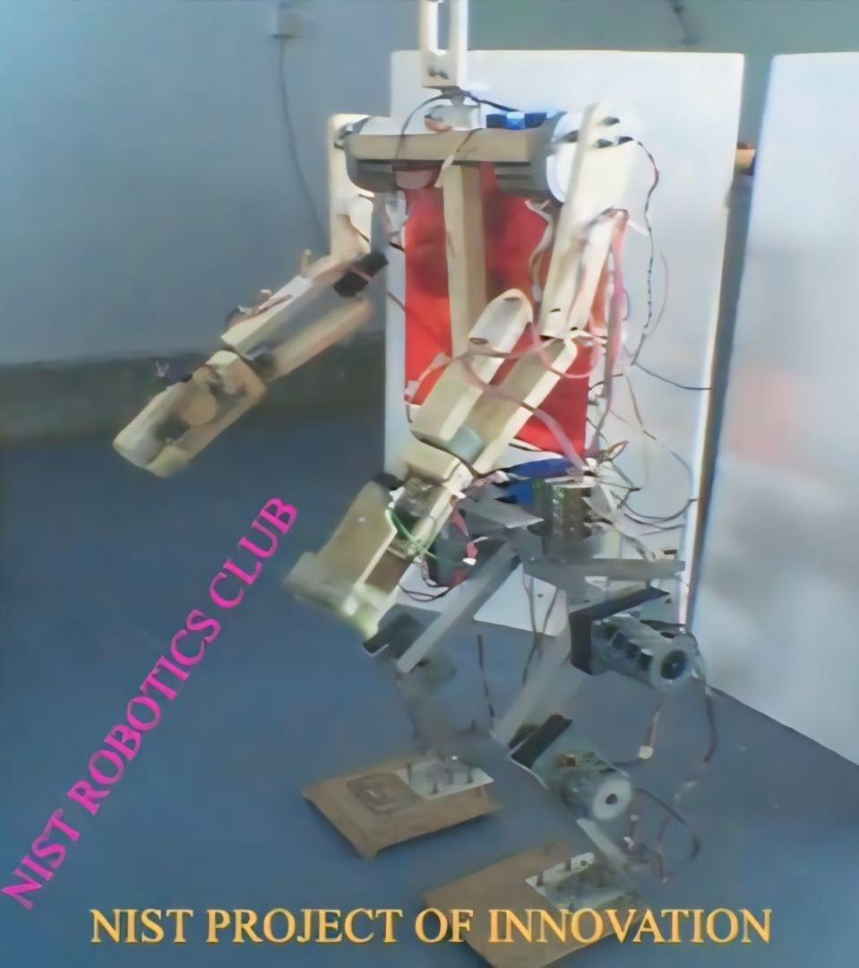
Project Overview
A human-like robot designed to emulate human movement and interaction patterns.
Technical Analysis
Powered by NRC AIThis project delves into the fascinating world of humanoid robotics, merging mechanical design with sophisticated electronics and programming. Building a human-like robot that emulates movement and interaction patterns is a significant undertaking, providing deep insights into kinematics, control systems, sensor integration, and real-time programming.
articleHumanoid Robot Project: Detailed Technical Analysis
label_important1. Technical Overview
The "Humanoid Robot" project aims to create a robot that mimics human morphology and movement. This involves several integrated technical subsystems working in harmony:
- Mechanical Structure (Body/Skeleton): This forms the physical framework of the robot, mimicking human limbs and joints. It's typically designed using CAD software and manufactured via 3D printing, laser cutting, or CNC machining. Joints are designed to allow rotational movement, similar to human joints (e.g., hip, knee, ankle, shoulder, elbow, wrist).
- Actuation System (Muscles/Motors): Servo motors are the primary actuators, converting electrical signals into precise angular movements. Each joint requires at least one servo (often more for multi-axis joints like hips or shoulders). High-torque digital servos are preferred for precision and strength.
- Sensing System (Eyes, Ears, Balance):
- Inertial Measurement Unit (IMU): Contains accelerometers and gyroscopes to sense the robot's orientation, acceleration, and angular velocity, crucial for balance and stable walking.
- Vision System (Camera): Allows the robot to perceive its environment, perform basic object recognition, facial detection, or track targets.
- Optional Sensors: Force sensors (for feet to detect ground contact), ultrasonic or IR sensors (for obstacle avoidance), microphones (for voice commands).
- Control System (Brain): This is the central processing unit, typically a microcontroller (like ESP32 or Arduino Mega) or a Single Board Computer (SBC) like Raspberry Pi. Its primary functions include:
- Kinematics: Calculating the joint angles required to achieve a desired end-effector position (Inverse Kinematics - IK) or calculating the end-effector position from given joint angles (Forward Kinematics - FK). This is fundamental for controlling complex movements like walking or waving.
- Motion Planning: Generating smooth, coordinated trajectories for multiple joints to perform actions (e.g., walking gaits, gestures).
- Sensor Fusion: Combining data from various sensors (e.g., IMU and camera) to get a comprehensive understanding of the robot's state and environment.
- Real-time Control: Sending precise PWM signals to servos at high frequency to ensure smooth and responsive movement.
- Interaction Logic: Implementing state machines for different behaviors (standing, walking, interacting).
- Power System: Provides stable and sufficient power to all components, especially the high-current-drawing servos. This typically involves high-capacity LiPo batteries and voltage regulators (Buck converters) to step down battery voltage to required levels (e.g., 5V for servos, 3.3V for the microcontroller).
- Communication: Enables remote control, data logging, and interaction with external systems (e.g., Wi-Fi, Bluetooth, Serial).
How it works technically:
- Input: Sensors (IMU, camera) gather data about the robot's state and surroundings.
- Processing: The control system (ESP32) receives sensor data. Based on pre-programmed instructions or higher-level commands (e.g., "walk forward"), it performs complex calculations (e.g., Inverse Kinematics) to determine the precise angle required for each of the robot's many joints.
- Actuation: The control system generates Pulse Width Modulation (PWM) signals for each servo. These signals instruct the servos to move to their calculated target angles.
- Movement: As servos move, the robot performs the desired action (e.g., takes a step, waves an arm).
- Feedback Loop: Sensor data is continuously fed back into the control system, allowing for real-time adjustments (e.g., maintaining balance using IMU data) and adapting to changes in the environment. This creates a closed-loop control system, essential for robust robotic behavior.
label_important2. Components Required
This list assumes a humanoid with approximately 12-18 Degrees of Freedom (DOF), allowing for basic bipedal walking and arm gestures.
Electronic Components:
- Microcontroller/SBC:
- ESP32 Development Board (e.g., ESP32-WROOM-32 or ESP32-CAM): Excellent for its Wi-Fi/Bluetooth, dual-core processing, and ample GPIOs for PWM. If using ESP32-CAM, the camera is integrated. If not, a separate camera module is needed.
- Actuators:
- High-Torque Digital Servo Motors (e.g., MG996R, DS3218, or for higher quality, digital servos like the "Robotis Dynamixel" series if budget allows): 12-18 units, depending on desired DOFs (e.g., 6 per leg for hip/knee/ankle motion, plus 1-2 per arm, 1 for head). Ensure they are capable of high torque for holding position.
- Sensors:
- MPU6050 (Accelerometer + Gyroscope IMU): For basic balance and orientation sensing. A BNO055 is more advanced (9-DOF, on-board sensor fusion).
- OV2640 Camera Module (if not using ESP32-CAM): For basic vision capabilities.
- Power Management:
- LiPo Battery (e.g., 3S 11.1V, 2000-5000mAh): Provides the primary power source. Choose based on estimated power consumption and desired runtime.
- Buck Converter (DC-DC Step-Down Converter, e.g., LM2596 or similar): To step down the LiPo voltage (11.1V) to 5V for servos and 3.3V for the ESP32. Multiple converters may be needed or a single one with sufficient current rating.
- LiPo Battery Charger: Essential for safe charging of LiPo batteries.
- Power Distribution Board (PDB) or Terminal Blocks: For cleanly distributing power to multiple servos.
- Capacitors (Electrolytic, 1000uF - 4700uF, 16V-25V): Placed across the servo power rail to smooth out voltage fluctuations caused by servo movement.
- Interconnects:
- Jumper Wires (Male-Male, Male-Female, Female-Female)
- Silicone Wires (various gauges, e.g., 20-22 AWG for servos, 24-26 AWG for signals)
- Breadboard or Perfboard: For prototyping circuits.
- Screw Terminal Blocks or JST Connectors: For secure power connections.
- Miscellaneous:
- Push Buttons: For mode selection or manual triggers.
- LEDs (various colors): For status indicators.
- Resistors (various values, e.g., 220 Ohm for LEDs)
- USB-to-Serial Converter (if using bare ESP32 module instead of dev board): For programming.
Mechanical Components & Materials:
- 3D Printed Parts: The entire robot frame, limbs, and joints (e.g., using PLA, PETG, or ABS filament for strength). Designs can be found on online repositories (e.g., Thingiverse) or created using CAD software (Fusion 360, SolidWorks, FreeCAD).
- Screws and Nuts (M2, M3, M4): To assemble the 3D printed parts and mount servos.
- Bearings (optional, but recommended for smoother joints): Small ball bearings for critical joints.
- Cable Ties/Velcro Straps: For cable management.
- Hot Glue/Super Glue: For securing minor components or reinforcing joints.
label_important3. Circuit Diagram Description
A detailed circuit diagram for a full humanoid robot is highly complex due to the large number of servos. Instead, I will describe the essential connections and general principles.
Key Principles:
- Separate Power for Servos: Servos draw significant current, especially when moving simultaneously. Powering them directly from the microcontroller's 5V pin can cause voltage sags, leading to brownouts and unstable behavior. Always use a separate, dedicated power supply for servos (via a Buck Converter from the main battery).
- Common Ground: All components (ESP32, servos, sensors, power supply) must share a common ground reference.
- Capacitors on Servo Power Rail: Large electrolytic capacitors (e.g., 1000uF or more) should be placed across the 5V and GND lines of the servo power rail, close to the power input. This helps filter out noise and provide instantaneous current bursts for sudden servo movements.
General Connections (Conceptual Diagram):
-
Main Power Supply (LiPo Battery)
- Connect the positive terminal of the LiPo battery to the input of the Buck Converters.
- Connect the negative terminal of the LiPo battery to the common ground rail.
-
Buck Converter 1 (for Servos)
- Input: LiPo Positive and LiPo Negative (Ground).
- Output: Set to 5V.
- Connect the 5V output to a dedicated Servo Power Rail (e.g., a bus bar, terminal block, or a strip of header pins on a perfboard).
- Connect the GND output to the Common Ground Rail.
- Place a large electrolytic capacitor across the 5V Servo Power Rail and Common Ground.
-
Buck Converter 2 (for ESP32 & Sensors)
- Input: LiPo Positive and LiPo Negative (Ground).
- Output: Set to 3.3V.
- Connect the 3.3V output to the 3V3/VCC pin of the ESP32.
- Connect the GND output to the Common Ground Rail.
- Alternatively, if your ESP32 board has an onboard 5V regulator and is rated for 5V input (e.g., VIN pin), you can power it directly from the 5V Buck Converter, which is also powering the servos. Check your specific ESP32 board's documentation.
-
ESP32 Development Board
- Power:
- VIN (or 5V): Connect to 5V output of Buck Converter 1 (if the ESP32 has an onboard 5V regulator and can accept it).
- 3V3/VCC: Connect to 3.3V output of Buck Converter 2.
- GND: Connect to Common Ground Rail.
- Servo Control Pins:
- Each servo's Signal Pin (usually yellow or white wire) connects to a dedicated GPIO pin on the ESP32. The library can use most GPIO pins capable of PWM, but some might have specific boot functions. For example, popular choices include GPIOs 12-19, 21-23, 25-27, 32-33. Avoid pins 0, 2, 4, 16, 17 during boot-up or as outputs if they affect flash mode. Check ESP32 pinout diagram for specific board.
ESP32Servo
- Each servo's Signal Pin (usually yellow or white wire) connects to a dedicated GPIO pin on the ESP32. The
- IMU (MPU6050/BNO055) Connections:
- VCC: Connect to 3.3V (from Buck Converter 2 or ESP32's 3.3V output).
- GND: Connect to Common Ground Rail.
- SDA (Serial Data): Connect to ESP32's GPIO 21 (I2C SDA).
- SCL (Serial Clock): Connect to ESP32's GPIO 22 (I2C SCL).
- Camera Module (if separate OV2640, typically 24-pin DVP interface):
- This is complex and usually requires specific ESP32-CAM module or a parallel interface. If using an ESP32-CAM board, the camera is integrated, and you only need to worry about the board's power and programming pins (see specific ESP32-CAM pinout for details on GPIO0 for programming, etc.).
- LEDs/Buttons:
- LED: Connect Anode to a GPIO pin via a 220 Ohm current-limiting resistor. Connect Cathode to Common Ground.
- Button: Connect one side to a GPIO pin. Connect the other side to Common Ground. Enable internal pull-up resistor in software.
- Power:
-
Servo Motors (example for one servo)
- Red Wire (VCC): Connect to 5V Servo Power Rail.
- Brown/Black Wire (GND): Connect to Common Ground Rail.
- Yellow/Orange/White Wire (Signal): Connect to an assigned ESP32 GPIO pin.
Visual Representation (Simplified):
LiPo Battery (e.g., 11.1V) +------------+ | | | | +----(-)----+-----> Common Ground Rail | +----(+)----> Buck Converter 1 (5V) ---------> Servo Power Rail (5V) | | +----(+)----> Buck Converter 2 (3.3V) -------> ESP32 3V3/VCC Pin | V Electrolytic Capacitor (on Servo Power Rail) | V +---------------------+ | | | ESP32 Board | | | Servo Signal --[GPIO_N] | Servo Signal --[GPIO_M] | ... (many servos) | | | IMU SDA -------[GPIO 21 (SDA)] | IMU SCL -------[GPIO 22 (SCL)] | IMU VCC (3.3V) | IMU GND | | | LED Anode ----- [GPIO_X] --- Resistor -- LED Cathode --> GND Button -------- [GPIO_Y] | | | | GND -----------------+----> Common Ground Rail +---------------------+ +----------------------------------------------------------------------------------+ | Servo 1 | Servo 2 | ... | Servo N | | | VCC | VCC | ... | VCC | ---------> Connected to Servo Power Rail (5V) | | GND | GND | ... | GND | ---------> Connected to Common Ground Rail | | Signal | Signal | ... | Signal | ---------> Connected to ESP32 GPIOs (as above)| +----------------------------------------------------------------------------------+
label_important4. Source Code (Arduino C++ for ESP32)
This code provides a basic framework. A full humanoid with inverse kinematics and complex gaits would be thousands of lines. This example focuses on:
- ESP32 setup for servo control.
- IMU (MPU6050) integration for basic orientation.
- Predefined poses/gestures using direct servo angle control.
- A placeholder for kinematics and more advanced control.
C++// ------------------------------------------------------------------- // Humanoid Robot Project - ESP32 Main Control Code // Language: Arduino C++ for ESP32 // Author: Your Name/Institution // Date: October 26, 2023 // Description: // This code provides the core control logic for a basic humanoid robot // using an ESP32. It demonstrates servo motor control, IMU data acquisition, // and simple predefined poses/gestures. // It lays the groundwork for more advanced features like kinematics. // ------------------------------------------------------------------- // 1. Include necessary libraries #include <ESP32Servo.h> // For controlling servo motors on ESP32 #include <Wire.h> // For I2C communication (used by MPU6050) #include <Adafruit_MPU6050.h> // For MPU6050 IMU sensor (Install via Arduino Library Manager) #include <Adafruit_Sensor.h> // Dependency for Adafruit_MPU6050 // 2. Define Robot Configuration (Adjust these based on your robot's design) // --- Servo Pin Definitions --- // Assign GPIO pins for each servo. ESP32 has many PWM-capable pins. // Example for a 12-DOF robot (6 per leg: HipYaw, HipPitch, KneePitch, AnklePitch, AnkleRoll, AnkleYaw - simplifying here to 3 per leg for Hip, Knee, Ankle Pitch) // Plus 2 arms with 3 servos each (ShoulderPitch, ShoulderRoll, ElbowPitch) // Plus 1 for neck/head // Total 3 + 3 + 3 + 3 + 1 = 13 servos. // Left Leg Servos (example pins) const int SERVO_L_HIP_PITCH_PIN = 13; // Left Hip Pitch const int SERVO_L_KNEE_PITCH_PIN = 12; // Left Knee Pitch const int SERVO_L_ANKLE_PITCH_PIN = 14; // Left Ankle Pitch // Right Leg Servos (example pins) const int SERVO_R_HIP_PITCH_PIN = 27; // Right Hip Pitch const int SERVO_R_KNEE_PITCH_PIN = 26; // Right Knee Pitch const int SERVO_R_ANKLE_PITCH_PIN = 25; // Right Ankle Pitch // Left Arm Servos (example pins) const int SERVO_L_SHOULDER_PITCH_PIN = 33; // Left Shoulder Pitch const int SERVO_L_SHOULDER_ROLL_PIN = 32; // Left Shoulder Roll const int SERVO_L_ELBOW_PITCH_PIN = 15; // Left Elbow Pitch // Right Arm Servos (example pins) const int SERVO_R_SHOULDER_PITCH_PIN = 5; // Right Shoulder Pitch const int SERVO_R_SHOULDER_ROLL_PIN = 18; // Right Shoulder Roll const int SERVO_R_ELBOW_PITCH_PIN = 19; // Right Elbow Pitch // Head Servo (example pin) const int SERVO_HEAD_YAW_PIN = 23; // Head Pan/Yaw // --- Servo Offset and Limits --- // These values are crucial for calibration. Adjust them after physical assembly. // A servo might not read 90 degrees as true center or have a full 0-180 range. // Min/Max angles define the physical limits to prevent damage. // Format: {PIN, OFFSET_ANGLE, MIN_ANGLE, MAX_ANGLE} struct ServoConfig { int pin; int offset; // Angle to add/subtract to center the servo (e.g., 90deg should be straight) int min_angle; // Physical min angle int max_angle; // Physical max angle }; ServoConfig servoConfigs[] = { {SERVO_L_HIP_PITCH_PIN, 0, 30, 150}, {SERVO_L_KNEE_PITCH_PIN, 0, 20, 160}, {SERVO_L_ANKLE_PITCH_PIN, 0, 30, 150}, {SERVO_R_HIP_PITCH_PIN, 0, 30, 150}, {SERVO_R_KNEE_PITCH_PIN, 0, 20, 160}, {SERVO_R_ANKLE_PITCH_PIN, 0, 30, 150}, {SERVO_L_SHOULDER_PITCH_PIN, 0, 0, 180}, {SERVO_L_SHOULDER_ROLL_PIN, 0, 0, 180}, {SERVO_L_ELBOW_PITCH_PIN, 0, 0, 180}, {SERVO_R_SHOULDER_PITCH_PIN, 0, 0, 180}, {SERVO_R_SHOULDER_ROLL_PIN, 0, 0, 180}, {SERVO_R_ELBOW_PITCH_PIN, 0, 0, 180}, {SERVO_HEAD_YAW_PIN, 0, 45, 135} }; const int NUM_SERVOS = sizeof(servoConfigs) / sizeof(servoConfigs[0]); // Array of Servo objects Servo servos[NUM_SERVOS]; // MPU6050 Sensor Object Adafruit_MPU6050 mpu; // --- Global Variables --- sensors_event_t a, g, temp; // MPU6050 sensor data variables // 3. Setup Function - Runs once when the ESP32 starts void setup() { Serial.begin(115200); while (!Serial); // Wait for serial connection Serial.println("Humanoid Robot Control System Initializing..."); // --- Initialize Servos --- // Allow the ESP32Servo library to control all pins ESP32PWM::allocateTimer(0); ESP32PWM::allocateTimer(1); ESP32PWM::allocateTimer(2); ESP32PWM::allocateTimer(3); for (int i = 0; i < NUM_SERVOS; i++) { servos[i].setPeriodHertz(50); // Standard 50Hz PWM for most hobby servos servos[i].attach(servoConfigs[i].pin, 500, 2500); // Attach servo to pin, with min/max pulse width (microseconds) Serial.print("Attached servo to pin: "); Serial.println(servoConfigs[i].pin); } // Set all servos to their neutral/initial pose (e.g., 90 degrees or adjusted by offset) // This is crucial to prevent jerky movements on startup. setAllServosToNeutral(); delay(1000); // Give servos time to reach position // --- Initialize MPU6050 --- Serial.println("Initializing MPU6050..."); if (!mpu.begin()) { Serial.println("Failed to find MPU6050 chip"); while (1) { delay(10); } // Halt if IMU not found } Serial.println("MPU6050 Found!"); mpu.setAccelerometerRange(MPU6050_RANGE_8_G); // Can be 2, 4, 8, 16 G mpu.setGyroRange(MPU6050_RANGE_500_DEG); // Can be 250, 500, 1000, 2000 DEG/s mpu.setFilterBandwidth(MPU6050_BAND_21_HZ); // Adjust for smoothness vs. responsiveness Serial.println("Initialization Complete. Robot Ready."); } // 4. Loop Function - Runs repeatedly void loop() { // --- Read Sensor Data --- mpu.getEvent(&a, &g, &temp); // Get new sensor events // Serial.print("Accelerometer X: "); Serial.print(a.acceleration.x); // Serial.print(" Y: "); Serial.print(a.acceleration.y); // Serial.print(" Z: "); Serial.print(a.acceleration.z); Serial.println(" m/s^2"); // Serial.print("Gyroscope X: "); Serial.print(g.gyro.x); // Serial.print(" Y: "); Serial.print(g.gyro.y); // Serial.print(" Z: "); Serial.print(g.gyro.z); Serial.println(" rad/s"); // --- Basic Balance Feedback (Conceptual) --- // A real balance algorithm would use PID control and Kalman filtering. // This is a very simplified example. // If the robot is tilting too much, try to correct (very basic example): if (a.acceleration.y > 1.5) { // Tilted right Serial.println("Tilting Right - Adjusting!"); // Example: shift weight left (adjust servo angles) // For proper balance, inverse kinematics and a stable gait is required. // This is just a conceptual placeholder. } else if (a.acceleration.y < -1.5) { // Tilted left Serial.println("Tilting Left - Adjusting!"); // Example: shift weight right } // --- Robot Action / State Machine --- // This is where you would implement your robot's behaviors. // You can use a switch-case statement or function calls based on a state variable. // Example: Cycle through some predefined actions static unsigned long lastActionTime = 0; static int currentAction = 0; const unsigned long ACTION_INTERVAL = 5000; // 5 seconds between actions if (millis() - lastActionTime > ACTION_INTERVAL) { lastActionTime = millis(); currentAction = (currentAction + 1) % 4; // Cycle through 4 actions (0, 1, 2, 3) Serial.print("Performing Action: "); switch (currentAction) { case 0: Serial.println("Standing Pose"); setRobotPose(POSE_STAND); break; case 1: Serial.println("Waving Right Arm"); waveArm(RIGHT_ARM, 2000); // Wave right arm for 2 seconds setRobotPose(POSE_STAND); // Return to stand after wave break; case 2: Serial.println("Sitting Down"); setRobotPose(POSE_SIT); break; case 3: Serial.println("Standing Up"); setRobotPose(POSE_STAND); break; } } // Add small delay to prevent busy-waiting and allow other tasks (like Wi-Fi) delay(10); } // 5. Helper Functions // Enum for predefined poses enum RobotPose { POSE_NEUTRAL, POSE_STAND, POSE_SIT // Add more poses like POSE_WALK_START, POSE_WALK_STEP_LEFT, etc. }; // Function to set all servos to a specific pose void setRobotPose(RobotPose pose) { int targetAngles[NUM_SERVOS]; // Array to hold target angles for each servo // Define angles for different poses. This is the "brain" for movements. // These angles are relative to the servo's physical mounting. // Calibration (offset and min/max) is critical here. switch (pose) { case POSE_NEUTRAL: // Set all servos to their neutral position (usually 90 degrees, adjusted by offset) // This is a good safe default. for (int i = 0; i < NUM_SERVOS; i++) { targetAngles[i] = 90 + servoConfigs[i].offset; } break; case POSE_STAND: // Angles for a stable standing pose (adjust based on your robot's geometry) // Left Leg targetAngles[0] = 90 + servoConfigs[0].offset; // L_HIP_PITCH (straight) targetAngles[1] = 90 + servoConfigs[1].offset; // L_KNEE_PITCH (straight) targetAngles[2] = 90 + servoConfigs[2].offset; // L_ANKLE_PITCH (straight) // Right Leg (mirrored) targetAngles[3] = 90 + servoConfigs[3].offset; // R_HIP_PITCH targetAngles[4] = 90 + servoConfigs[4].offset; // R_KNEE_PITCH targetAngles[5] = 90 + servoConfigs[5].offset; // R_ANKLE_PITCH // Arms (relaxed) targetAngles[6] = 90 + servoConfigs[6].offset; // L_SHOULDER_PITCH targetAngles[7] = 90 + servoConfigs[7].offset; // L_SHOULDER_ROLL targetAngles[8] = 90 + servoConfigs[8].offset; // L_ELBOW_PITCH targetAngles[9] = 90 + servoConfigs[9].offset; // R_SHOULDER_PITCH targetAngles[10] = 90 + servoConfigs[10].offset; // R_SHOULDER_ROLL targetAngles[11] = 90 + servoConfigs[11].offset; // R_ELBOW_PITCH // Head targetAngles[12] = 90 + servoConfigs[12].offset; // HEAD_YAW break; case POSE_SIT: // Angles for a sitting pose (legs bent, robot lowers itself) // This will require careful tuning to ensure stability. // Left Leg targetAngles[0] = 45 + servoConfigs[0].offset; // L_HIP_PITCH (bent forward) targetAngles[1] = 135 + servoConfigs[1].offset; // L_KNEE_PITCH (bent back) targetAngles[2] = 45 + servoConfigs[2].offset; // L_ANKLE_PITCH (adjust for balance) // Right Leg (mirrored) targetAngles[3] = 135 + servoConfigs[3].offset; // R_HIP_PITCH targetAngles[4] = 45 + servoConfigs[4].offset; // R_KNEE_PITCH targetAngles[5] = 135 + servoConfigs[5].offset; // R_ANKLE_PITCH // Arms (relaxed, or on lap) targetAngles[6] = 90 + servoConfigs[6].offset; targetAngles[7] = 90 + servoConfigs[7].offset; targetAngles[8] = 90 + servoConfigs[8].offset; targetAngles[9] = 90 + servoConfigs[9].offset; targetAngles[10] = 90 + servoConfigs[10].offset; targetAngles[11] = 90 + servoConfigs[11].offset; // Head targetAngles[12] = 90 + servoConfigs[12].offset; break; // Add more cases for walking, waving, etc. } // Apply the calculated angles to the servos for (int i = 0; i < NUM_SERVOS; i++) { // Constrain angle to physical limits defined in servoConfigs int finalAngle = constrain(targetAngles[i], servoConfigs[i].min_angle, servoConfigs[i].max_angle); servos[i].write(finalAngle); // Serial.print("Setting servo "); Serial.print(i); Serial.print(" to "); Serial.println(finalAngle); } } // Function to move all servos to their neutral position void setAllServosToNeutral() { for (int i = 0; i < NUM_SERVOS; i++) { int neutralAngle = 90 + servoConfigs[i].offset; neutralAngle = constrain(neutralAngle, servoConfigs[i].min_angle, servoConfigs[i].max_angle); servos[i].write(neutralAngle); } } // Enum for arm selection enum ArmSide { LEFT_ARM, RIGHT_ARM }; // Function for a simple waving gesture void waveArm(ArmSide side, unsigned long durationMs) { int shoulderPitchIdx, shoulderRollIdx, elbowPitchIdx; if (side == LEFT_ARM) { shoulderPitchIdx = 6; // Index for SERVO_L_SHOULDER_PITCH_PIN in servoConfigs shoulderRollIdx = 7; elbowPitchIdx = 8; } else { // RIGHT_ARM shoulderPitchIdx = 9; // Index for SERVO_R_SHOULDER_PITCH_PIN shoulderRollIdx = 10; elbowPitchIdx = 11; } // Waving motion sequence int waveCount = 3; unsigned long delayPerWave = durationMs / (waveCount * 2); // Up and down motion // Lift arm to waving position servos[shoulderPitchIdx].write(45 + servoConfigs[shoulderPitchIdx].offset); // Lift arm up servos[shoulderRollIdx].write(90 + servoConfigs[shoulderRollIdx].offset); // Keep straight servos[elbowPitchIdx].write(150 + servoConfigs[elbowPitchIdx].offset); // Bend elbow slightly delay(500); // Pause for arm to reach position // Perform wave motion for (int i = 0; i < waveCount; i++) { // Wave out servos[shoulderRollIdx].write(45 + servoConfigs[shoulderRollIdx].offset); // Rotate arm delay(delayPerWave); // Wave in servos[shoulderRollIdx].write(135 + servoConfigs[shoulderRollIdx].offset); // Rotate arm back delay(delayPerWave); } // Return arm to standing pose position // This will be handled by the next call to setRobotPose(POSE_STAND) in loop() } // --- Placeholder for Kinematics (Forward and Inverse) --- // These functions would be very complex and often implemented in separate files or using dedicated libraries. // They require accurate robot dimensions and joint definitions (Denavit-Hartenberg parameters). /* // Function to calculate Forward Kinematics (FK) // Input: Joint angles // Output: End effector (e.g., foot, hand) position and orientation in global coordinates Point3D calculateForwardKinematics(int servoAngles[]) { // Implement complex matrix transformations here // ... return {x, y, z}; // Example return type } // Function to calculate Inverse Kinematics (IK) // Input: Desired end effector (e.g., foot, hand) position and orientation // Output: Required joint angles for all relevant servos bool calculateInverseKinematics(Point3D targetPos, int desiredAngles[]) { // This is computationally intensive and often involves iterative solvers // or analytical solutions for specific robot geometries. // ... // If successful, populate desiredAngles[] and return true. return true; // Or false if unreachable } */ // --- Placeholder for Gait Generation --- // For walking, you'd define a sequence of poses and transitions (a gait cycle). /* void performWalkStep(ArmSide leadingLeg) { // Sequence of poses: // 1. Shift weight to support leg // 2. Lift swing leg // 3. Move swing leg forward // 4. Place swing leg down // 5. Shift weight back to center // ... repeat for other leg } */
label_important5. Source Code Structure
The provided source code is structured for clarity and maintainability:
- (or
main.ino): This is the primary file containing the.cppandsetup()functions, which are the entry points for Arduino programs. It orchestrates the overall robot behavior.loop()- Includes: At the top, including necessary libraries (,
ESP32Servo.h,Wire.h,Adafruit_MPU6050.h).Adafruit_Sensor.h - Robot Configuration: Global constants for servo pin assignments, struct to hold calibration data (offset, min/max angles) for each servo, and an array of
ServoConfigobjects.Servo - Sensor Objects: Instantiation of sensor objects (e.g., ).
Adafruit_MPU6050 mpu; - Global Variables: Any variables that need to be accessible across functions (e.g., sensor data variables, state machine variables).
- Function: Initializes serial communication, attaches all servo motors to their respective pins, configures the
setup()library's timers, and initializes the IMU sensor. It also sets an initial safe pose.ESP32Servo - Function: The main execution loop. It continuously reads sensor data, implements basic feedback (e.g., for balance), and manages the robot's high-level actions through a simple state machine that cycles through predefined poses.
loop() - Helper Functions: Contains modular functions for specific tasks like:
- : Applies a set of predefined angles to all servos to achieve a specific robot pose (e.g., stand, sit).
setRobotPose(RobotPose pose) - : A utility to move all servos to a default neutral position (important for safety and calibration).
setAllServosToNeutral() - : Implements a simple waving gesture for an arm.
waveArm(ArmSide side, unsigned long durationMs) - Placeholders for Kinematics/Gait: Comments indicate where more advanced functions like ,
calculateForwardKinematics(), andcalculateInverseKinematics()would be implemented. These are typically the most complex parts of humanoid control.performWalkStep()
- Includes: At the top, including necessary libraries (
Libraries Needed:
- : Essential for controlling servo motors with the ESP32's advanced PWM capabilities. Installable via Arduino Library Manager.
ESP32Servo - : Standard Arduino library for I2C (Two-Wire Interface) communication, used by the MPU6050. Comes pre-installed with Arduino IDE.
Wire.h - : An easy-to-use library for interacting with the MPU6050 IMU. Installable via Arduino Library Manager.
Adafruit_MPU6050 - : A dependency for
Adafruit_Sensor, providing a unified sensor API. Installable via Arduino Library Manager.Adafruit_MPU6050
Key Functions and Their Roles:
- : System initialization.
setup() - : Main control loop, continuously executing robot logic.
loop() - : Translates a high-level pose command into individual servo angle commands. This function is where the "choreography" of the robot's movements is defined.
setRobotPose(RobotPose pose) - : Ensures a safe, known starting position for all servos.
setAllServosToNeutral() - : Demonstrates a multi-servo coordinated movement for a gesture.
waveArm(ArmSide side, unsigned long durationMs) - : Initializes the IMU sensor.
mpu.begin() - : Reads accelerometer, gyroscope, and temperature data from the IMU.
mpu.getEvent(&a, &g, &temp) - : Configures a servo to a specific GPIO pin and sets its pulse width limits.
servo.attach(pin, minPulse, maxPulse) - : Commands a servo to move to a specific angle (0-180 degrees).
servo.write(angle) - : Arduino function to limit a value within a specified range, crucial for preventing servos from exceeding their physical limits.
constrain(value, min, max)
label_important6. Step-by-Step Implementation Guide
6.1. Hardware Assembly Steps
- Gather Components: Ensure all listed components (3D printed parts, servos, ESP32, IMU, power components, wires, screws) are available and checked.
- Assemble Robot Skeleton:
- Start with the torso, then attach hip/pelvis sections.
- Mount servo motors into their designated slots in the 3D printed parts. Ensure they are aligned correctly (e.g., output shaft at the pivot point of the joint).
- Attach limb segments (thighs, shins, feet, upper arms, forearms, hands, head) using screws, connecting them to the servo horns.
- Crucial: Servo Centering: Before final attachment, connect each servo individually to a basic servo tester or run a small code on the ESP32 that sets each servo to its mechanical center (usually 90 degrees). Then, physically align the robot limb to its straight, neutral position and secure the servo horn. This is critical for later kinematics.
setup()
- Power Distribution Wiring:
- Mount your LiPo battery securely within the robot's chassis.
- Connect the LiPo battery to the input of your Buck Converters.
- Wire the 5V Buck Converter output to a power distribution board or terminal block. This will be your Servo Power Rail.
- Wire the 3.3V Buck Converter output to another terminal block for ESP32/sensor power, or directly to the ESP32's 3V3 pin.
- Ensure all grounds (LiPo, Buck converters, Servo Power Rail, ESP32) are connected to a Common Ground Rail.
- Add large electrolytic capacitors across the 5V Servo Power Rail and Common Ground.
- Microcontroller & Sensor Mounting:
- Mount the ESP32 securely within the robot's torso or head.
- Mount the MPU6050 IMU sensor on a stable, central part of the robot's torso. Its orientation is important for accurate readings; note which axis is X, Y, Z for your robot's orientation.
- If using a separate camera, mount it in the head.
- Servo Wiring:
- For each servo:
- Connect its Red wire (VCC) to the 5V Servo Power Rail.
- Connect its Brown/Black wire (GND) to the Common Ground Rail.
- Connect its Yellow/Orange/White wire (Signal) to its assigned ESP32 GPIO pin. Keep wires tidy and use cable ties.
- For each servo:
- IMU Wiring:
- Connect MPU6050 VCC to ESP32 3.3V or 3.3V Buck Converter output.
- Connect MPU6050 GND to Common Ground.
- Connect MPU6050 SDA to ESP32 GPIO 21.
- Connect MPU6050 SCL to ESP32 GPIO 22.
- Final Checks: Double-check all power connections for polarity and short circuits. Verify all signal connections are to the correct pins.
6.2. Software Setup and Programming
- Install Arduino IDE: Download and install the latest Arduino IDE from arduino.cc.
- Add ESP32 Board Support:
- Go to .
File -> Preferences - In "Additional Boards Manager URLs", add:
https://raw.githubusercontent.com/espressif/arduino-esp32/gh-pages/package_esp32_index.json - Go to . Search for "esp32" and install "esp32 by Espressif Systems".
Tools -> Board -> Boards Manager...
- Go to
- Install Libraries:
- Go to .
Sketch -> Include Library -> Manage Libraries... - Search for and install:
ESP32Servo- (and its dependency
Adafruit MPU6050).Adafruit Unified Sensor
- Go to
- Open Source Code: Copy the provided C++ code into a new Arduino sketch.
- Configure Code:
- Servo Pin Definitions: Carefully review and adjust the , etc., constants to match the actual GPIO pins you used in your wiring.
SERVO_L_HIP_PITCH_PIN - Servo Offsets/Limits: This is crucial. After initial setup, you'll calibrate these values. For now, leave offsets at 0 and min/max at 0/180.
- Servo Pin Definitions: Carefully review and adjust the
- Connect ESP32:
- Connect your ESP32 board to your computer via USB.
- Go to and select your specific ESP32 Dev Module (e.g., "ESP32 Dev Module").
Tools -> Board - Go to and select the correct COM port for your ESP32.
Tools -> Port
- Upload Code:
- Click the "Upload" button (right arrow icon) in the Arduino IDE.
- For some ESP32 boards (especially ESP32-CAM), you might need to press and hold the "BOOT" button on the board while uploading, then release it after upload starts.
6.3. Testing and Calibration Procedures
Safety First: Always have a way to quickly cut power to the robot during testing (e.g., a power switch, easily removable battery connector). Servos can break themselves or the robot if commanded incorrectly.
- Initial Power-On Test:
- With the code uploaded (and in
setAllServosToNeutral()): Connect the battery.setup() - Observe if all servos move to their approximate neutral position without excessive buzzing or stalling. If a servo vibrates intensely, check its wiring and power.
- With the code uploaded (and
- Individual Servo Calibration:
- Modify the function to iterate through each servo, setting it to 0, 90, and 180 degrees, observing its actual physical range.
setup() - Example:
C++
// In setup() after servo.attach() loop for (int i = 0; i < NUM_SERVOS; i++) { Serial.print("Calibrating servo pin: "); Serial.println(servoConfigs[i].pin); servos[i].write(90); // Go to nominal center delay(1000); servos[i].write(0); // Go to one extreme delay(1000); servos[i].write(180); // Go to other extreme delay(1000); servos[i].write(90); // Back to center delay(1000); Serial.println("Adjust offset in servoConfigs[] array based on physical alignment."); Serial.println("Then, verify min/max angles to avoid hitting mechanical stops."); delay(2000); // Pause for user to observe } // Then proceed to MPU initialization - Adjust : For each servo, find the
offsetvalue inoffsetsuch that whenservoConfigs[]is called, the limb segment is in its perfectly straight or desired neutral position.servos[i].write(90 + offset); - Adjust /
min_angle: Physically move each joint to its absolute mechanical limits without forcing it. Note down these safe minimum and maximum angles and updatemax_angleandmin_angleinmax_angle. This prevents the servo from trying to push past a physical stop, which can damage it.servoConfigs[] - Repeat this process for every single servo until they are all correctly calibrated. This is the most time-consuming but critical part.
- Modify the
- IMU Calibration:
- With the MPU6050 initialized, open the Serial Monitor.
- Place the robot on a flat, level surface.
- Observe the ,
a.acceleration.x,yvalues.zshould be close to -9.81 m/s^2 (gravity). X and Y should be close to 0. If they are not, you might need to apply software offsets (thoughzoften handles basic factory calibration well).Adafruit_MPU6050 - For more advanced calibration (e.g., for yaw drift), consider using sketches or a library that includes a full IMU fusion algorithm (e.g., Mahony or Madgwick filter).
MPU6050_ calibration
- Basic Pose Testing:
- Uncomment the function's action cycling.
loop() - Observe the robot as it cycles through ,
POSE_STAND,POSE_SIT.waveArm() - Adjust the angles defined within and
setRobotPose()functions to refine the poses for stability and aesthetics.waveArm() - Pay close attention to stability, especially when transitioning poses. The robot should not fall over.
- Uncomment the
- Gait/Movement Testing (if implemented):
- If you've started implementing walking gaits, test them slowly and incrementally.
- Start with very small steps. Monitor power consumption and servo temperatures.
- Use a safety harness or have someone ready to catch the robot if it loses balance.
label_important7. Challenges and Solutions
-
Challenge: Power Management & Brownouts
- Problem: Servos, especially high-torque ones, draw large current spikes when starting, stopping, or under load. This can cause voltage drops on the power rail (brownouts), leading to microcontroller resets or erratic servo behavior.
- Solution:
- Separate Power Supply: Always use a dedicated, high-current-capable power supply (e.g., a robust LiPo battery with a proper buck converter) for servos, completely separate from the microcontroller's supply, with only grounds connected.
- Capacitors: Add large electrolytic capacitors (1000uF - 4700uF per ~4-6 servos) across the servo power rail close to the distribution point to absorb voltage fluctuations.
- Thick Wires: Use sufficiently thick wires (e.g., 20-22 AWG) for power distribution to minimize voltage drop.
- Gradual Movements: In software, avoid sudden, simultaneous movements of many servos. Implement smooth transitions using or non-blocking timing.
delay()
-
Challenge: Servo Precision, Backlash, and Calibration
- Problem: Hobby servos often lack precision, have mechanical backlash, and their "90-degree" center might not align with the desired physical straight position. Inaccurate calibration leads to skewed poses and unstable movements.
- Solution:
- Meticulous Calibration: The and
offset/min_anglevalues inmax_angleare paramount. Spend significant time calibrating each servo.servoConfigs[] - Digital Servos: If budget allows, use digital servos. They offer better precision, holding torque, and often provide feedback (though this requires more advanced protocols).
- Mechanical Design: Design joints to minimize backlash and provide clear physical stops to prevent over-rotation.
- Software Smoothing: Implement smooth angle transitions (e.g., using loops to increment/decrement angles slowly) instead of immediate
forcalls.servo.write()
- Meticulous Calibration: The
-
Challenge: Kinematics Complexity (Inverse Kinematics - IK)
- Problem: Calculating the precise angles for many interdependent joints to achieve a desired end-effector position (e.g., placing a foot correctly for walking) is mathematically complex.
- Solution:
- Start Simple: Begin with Forward Kinematics (FK) for understanding. For initial movements, use predefined poses and direct commands.
servo.write() - Pre-computed Gaits: For walking, define a sequence of key poses that form a stable gait cycle.
- Kinematics Libraries/Tools: For true IK, consider using dedicated libraries (e.g., for inverse kinematics in robotics, or often, external tools like Python scripts with
FastLEDorIKPyto generate joint angles offline, which are then uploaded to the robot).Robotics Toolbox - Simulators: Use robotic simulators (Gazebo, Webots) for testing kinematics and gaits before deploying to hardware.
- Start Simple: Begin with Forward Kinematics (FK) for understanding. For initial movements, use predefined poses and direct
-
Challenge: Balance and Stability
- Problem: Bipedal robots are inherently unstable. Dynamic walking and maintaining balance are very difficult.
- Solution:
- Static Stability: Design the robot with a wide stance when standing or moving slowly. Prioritize positions where the robot's center of gravity (CoG) is always within its support polygon (area defined by feet on the ground).
- IMU Feedback: Use IMU data (accelerometer for tilt, gyroscope for angular velocity) in a basic feedback loop. If the robot tilts, slightly shift its CoG back towards the center by adjusting hip/ankle servos.
- PID Control: For more robust balance, implement a PID (Proportional-Integral-Derivative) controller that uses IMU error (deviation from upright) to adjust servo angles.
- Momentum Management: For dynamic walking, this becomes critical, involving complex algorithms. Start with slow, deliberate movements.
-
Challenge: Mechanical Durability & Stress Points
- Problem: 3D printed parts, especially at joints or where servos attach, can wear out or break under repeated stress.
- Solution:
- Stronger Materials: Print critical parts with stronger filaments like PETG, ABS, or Nylon instead of PLA.
- Design Reinforcements: Add fillets, thicker walls, or internal bracing at high-stress areas during CAD design.
- Proper Fasteners: Use appropriate screws and nuts, and consider brass inserts for screw threads in plastic.
- Bearings: Integrate small ball bearings at high-friction rotational joints to reduce wear and improve smoothness.
-
Challenge: Debugging Complex Systems
- Problem: Pinpointing issues in a system with many interconnected hardware and software components can be difficult.
- Solution:
- Modular Development: Test each subsystem (power, a single servo, IMU) independently before integrating.
- Serial Debugging: Use extensively to output sensor readings, servo target angles, and state variables to the Serial Monitor.
Serial.print() - Incremental Approach: Build functionality piece by piece. Get standing working, then waving, then simple steps. Don't try to implement everything at once.
- Version Control: Use Git to track changes in your code, allowing you to revert to previous working versions.
label_important8. Learning Outcomes
By undertaking this "Humanoid Robot" project, students will gain comprehensive knowledge and practical skills across multiple engineering disciplines:
- Electronics & Hardware Interfacing:
- Power Management: Understanding high-current drawing components (servos), designing robust power distribution systems, using LiPo batteries, buck converters, and capacitors.
- Sensor Integration: Interfacing with I2C sensors (IMU), understanding their data outputs (acceleration, angular velocity), and basic sensor fusion.
- Actuator Control: Detailed understanding of servo motors (PWM control, torque, speed, precision) and their real-world application.
- Microcontroller Programming: Deep dive into ESP32 capabilities (multi-core, Wi-Fi/Bluetooth, extensive GPIOs, timers for PWM).
- Robotics Fundamentals:
- Kinematics (Forward & Inverse): Grasping the mathematical relationship between joint angles and end-effector positions. Even if not fully implemented, the conceptual understanding is crucial.
- Motion Planning & Control: Developing algorithms for generating smooth and coordinated movements for multiple DOFs.
- Gait Generation: Understanding the principles of bipedal walking and designing basic gait cycles.
- Balance and Stability: Learning about static and dynamic stability, and basic methods for maintaining balance using sensor feedback.
- Feedback Control Systems: Implementing basic closed-loop control (e.g., using IMU for balance correction).
- Programming Skills:
- C++ & Arduino IDE: Proficiently using the Arduino development environment and writing structured C++ code.
- Library Utilization: Effectively using existing libraries for common hardware components (servos, IMU).
- Object-Oriented Programming (OOP): Understanding how objects (like or
Servo) encapsulate data and behavior.MPU6050 - State Machines: Implementing logical state transitions for robot behaviors.
- Debugging & Troubleshooting: Developing systematic approaches to identify and resolve issues in complex hardware-software systems.
- Mechanical Design & Assembly:
- Understanding Joint Design: How different joint types mimic human articulation.
- Physical Assembly: Practical experience in assembling complex mechanical systems, including servo mounting, wiring, and cable management.
- Calibration: The importance of precise physical and software calibration for robotic performance.
- Systems Integration: The overarching challenge and learning outcome of bringing together disparate hardware and software components to create a functional, intelligent system.
- Problem-Solving: Developing critical thinking skills to analyze problems (e.g., robot instability, power issues) and devise effective solutions.
label_important9. Extensions and Improvements
This project can be expanded significantly for more advanced learning:
- Full Inverse Kinematics (IK) Implementation:
- Implement an analytical or iterative IK solver for the robot's legs and arms. This is a major undertaking but fundamental for precise pose control and dynamic walking.
- Integrate a kinematics library (e.g., for MATLAB/Python, or a custom C++ implementation) to calculate joint angles for desired foot/hand positions.
Robotics Toolbox
- Advanced Balance Control:
- PID Control: Implement a PID controller using IMU pitch and roll data to actively stabilize the robot by adjusting hip/ankle joint angles.
- Kalman Filtering/Complementary Filter: Use these techniques to fuse accelerometer and gyroscope data for more accurate and stable orientation estimation.
- Zero Moment Point (ZMP): For true dynamic walking, delve into ZMP analysis to plan stable foot trajectories.
- Sophisticated Gait Generation:
- Develop more natural and stable walking gaits (e.g., trot, walk, turn, side-step).
- Implement smooth gait transitions and speed control.
- Consider generating gaits offline using simulation software and uploading trajectory points.
- Vision System Enhancement:
- Object Detection/Tracking: Use OpenCV (if using Raspberry Pi or higher-end ESP32 modules) for real-time object detection (e.g., detecting a ball, a person).
- Facial Recognition: Implement basic facial recognition for personalized interactions.
- Depth Sensing: Integrate a small LiDAR or Time-of-Flight (ToF) sensor (e.g., VL53L0X) for rudimentary depth perception and obstacle avoidance.
- Voice Interface:
- Speech Recognition: Integrate a compact speech recognition module (e.g., a simple keyword spotter with ESP32-LyraT, or cloud-based APIs with Wi-Fi).
- Text-to-Speech (TTS): Allow the robot to speak pre-programmed phrases or responses.
- Remote Control & Communication:
- Web Interface: Create a simple web server on the ESP32 to allow control via a web browser on a smartphone or PC.
- Bluetooth Control: Develop an Android/iOS app for control via Bluetooth.
- ROS (Robot Operating System) Integration: For very advanced projects, integrate the ESP32 into a ROS ecosystem running on a companion computer (like a Raspberry Pi) to leverage ROS tools for navigation, planning, and high-level control.
- Tactile Sensing:
- Add Force Sensitive Resistors (FSRs) to the feet to detect ground contact and weight distribution for more stable walking.
- Add FSRs or other tactile sensors to the hands for grip control.
- Machine Learning / AI Integration:
- Reinforcement Learning: Explore using RL for gait optimization or learning new behaviors.
- Neural Networks: For more robust object recognition or behavior generation (e.g., tinyML on ESP32).
- Energy Efficiency:
- Implement power-saving modes for servos when idle.
- Optimize servo movement trajectories to minimize energy consumption.
- Modular Design:
- Break down the code into separate (header) and
.h(source) files for each module (e.g.,.cpp,Kinematics.cpp,GaitControl.cpp). This improves code organization for large projects.SensorManager.cpp
- Break down the code into separate
This project is a fantastic starting point for understanding the complexities and rewards of robotics engineering. By iteratively building upon the foundational elements, students can create increasingly sophisticated and autonomous humanoid robots.
infoThis analysis is generated by AI and should be used as a learning guide. Always verify technical details.