


Human Following Bot
Human Following Bot is an autonomous engineering project developed by the NIST Robotics Club (NRC) at NIST University, Berhampur. An intelligent robot that can detect and follow humans autonomously using computer vision algorithms.

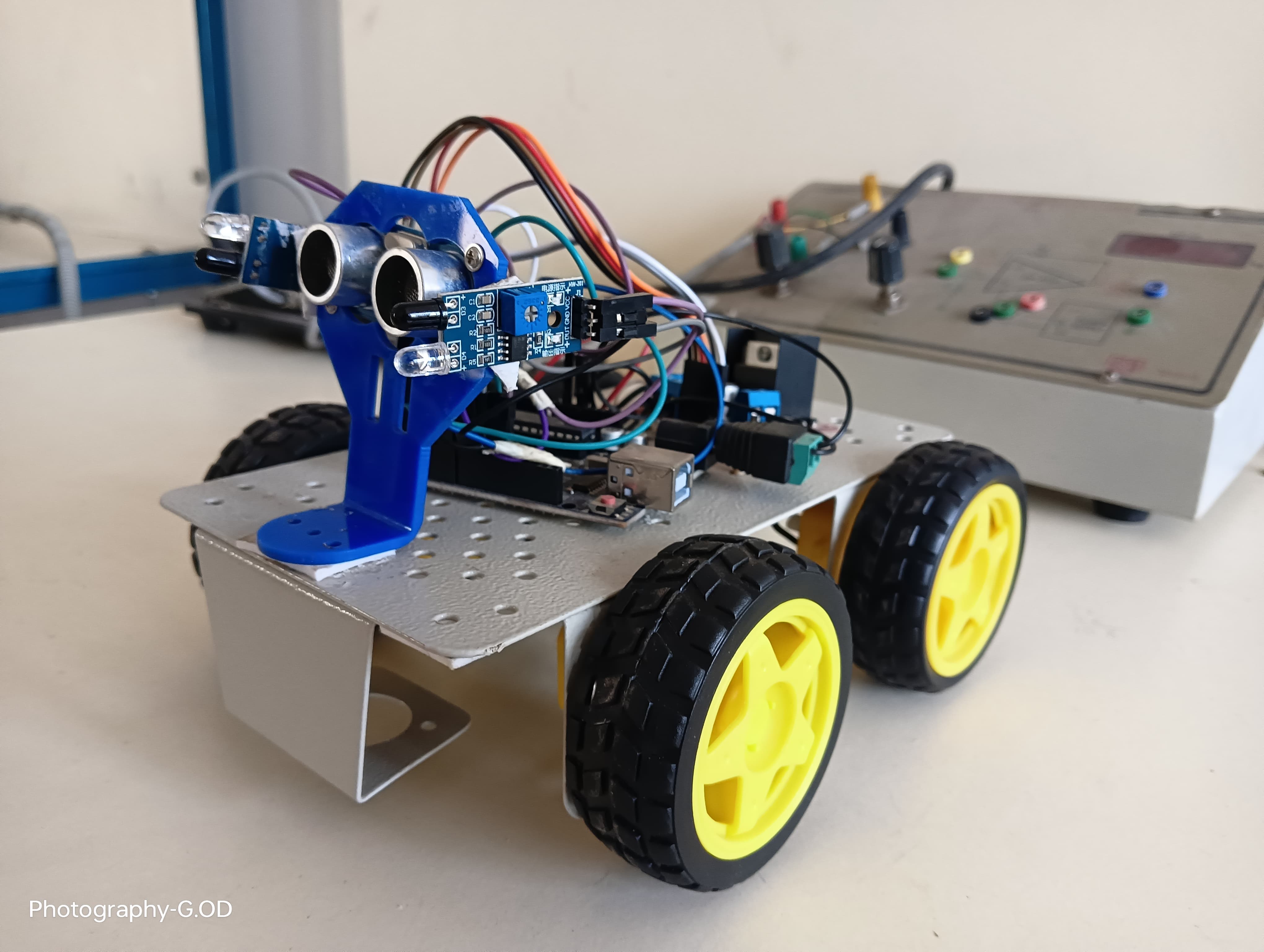
Project Overview
An intelligent robot that can detect and follow humans autonomously using computer vision algorithms.
Technical Analysis
Powered by NRC AIAs an expert in robotics and electronics, I'm delighted to provide a detailed technical analysis for your "Human Following Bot" project. This project is an excellent blend of computer vision, embedded systems, and robotic control, offering a rich learning experience for engineering students.
articleHuman Following Bot: Detailed Technical Analysis
label_important1. Technical Overview
The "Human Following Bot" project involves an intelligent mobile robot that autonomously detects and follows a human using real-time computer vision. The core idea revolves around a closed-loop control system: sense, process, and act.
- Sensing (Input): The primary sensor is a camera (e.g., Raspberry Pi Camera Module). It continuously captures video frames of the robot's surroundings.
- Processing (Brain): A single-board computer (SBC) like the Raspberry Pi acts as the robot's brain.
- Computer Vision: Image processing algorithms are applied to the captured frames to detect human figures. For simplicity and real-time performance on an SBC, techniques like Haar Cascades (for frontal/profile faces or full bodies) or more advanced, lightweight deep learning models (e.g., MobileNet SSD, MediaPipe BlazeFace/Pose) can be used.
- Target Identification: Once a human is detected, the algorithm identifies their bounding box (location and size) within the frame.
- Position and Distance Estimation:
- Horizontal Alignment: The horizontal center of the detected human's bounding box is compared to the horizontal center of the camera's field of view. An offset indicates whether the human is to the left, right, or center.
- Distance Estimation: The size of the bounding box (specifically, its height or area) can be inversely proportional to the distance of the human from the camera. A larger bounding box implies the human is closer, and a smaller one implies they are further away. A target size or range is pre-defined for optimal following distance.
- Control Command Generation: Based on the calculated horizontal offset and estimated distance, control commands are generated for the robot's motors.
- If the human is centered horizontally but too far, the robot moves forward.
- If too close, it stops or moves backward slightly.
- If to the left, it turns left.
- If to the right, it turns right.
- A combination of these commands (e.g., moving forward while slightly turning) is often required.
- Actuation (Output): DC geared motors with wheels are used for locomotion. A motor driver (e.g., L298N, DRV8825) interfaces the low-power control signals from the Raspberry Pi's GPIO pins to the higher-power requirements of the motors.
- Control Loop: The entire process (capture, detect, calculate, act) runs in a continuous loop. This feedback mechanism allows the robot to constantly adjust its movement based on the human's position, ensuring it maintains following. A Proportional-Integral-Derivative (PID) controller or a simpler Proportional (P) controller is often implemented to refine motor speeds and achieve smooth, stable following.
label_important2. Components Required
Here's a comprehensive list of components:
- Robot Chassis:
- Chassis: Two-wheel drive acrylic or metal chassis kit.
- DC Geared Motors (x2): Typically 60-150 RPM with encoder (optional but recommended for odometry).
- Wheels (x2): Compatible with the motors.
- Caster Wheel (x1): For stability and balancing the robot.
- Motor Brackets (x2): To mount motors to the chassis.
- Electronics (Core):
- Single-Board Computer (SBC): Raspberry Pi 3B+/4B (recommended for its processing power and GPIOs).
- Raspberry Pi Camera Module: V2 (8MP) or compatible CSI camera.
- Motor Driver Module: L298N H-Bridge Module (common and robust) or DRV8833/DRV8825 (more efficient, for smaller motors).
- Power Bank/Battery:
- For Raspberry Pi: 5V, 3A USB Power Bank (or LiPo battery with suitable buck converter).
- For Motors: 7.4V (2S) or 11.1V (3S) LiPo Battery (e.g., 2000-3000mAh) or AA/AAA battery holder (6-8 cells).
- DC-DC Buck Converter: MP1584EN or LM2596 (if using a higher voltage battery for Pi). Converts motor battery voltage down to stable 5V for Raspberry Pi.
- Wiring & Miscellaneous:
- Jumper Wires: Male-to-male, female-to-male, female-to-female for connections.
- Breadboard (optional): For prototyping and temporary connections.
- MicroSD Card: 16GB or 32GB Class 10 (for Raspberry Pi OS).
- USB Keyboard/Mouse/Monitor (for initial setup): Or headless setup with SSH.
- Power Adapter: For charging batteries.
- Screws and Nuts: For assembly.
- Zip Ties/Velcro: For cable management and component securing.
label_important3. Circuit Diagram Description
This description focuses on a Raspberry Pi 3B+/4B with an L298N motor driver.
Power Distribution:
- Motor Power: Connect the positive (+) terminal of your motor battery (e.g., 7.4V LiPo) to the (or
+12V) terminal on the L298N module. Connect the negative (-) terminal of the motor battery to the+VCCterminal on the L298N module.GND - Raspberry Pi Power:
- Option 1 (Separate Power Bank): Connect a 5V/3A USB power bank directly to the Raspberry Pi's micro USB (or USB-C for Pi 4) power input. This is simplest.
- Option 2 (Shared Battery with Buck Converter): If using the same battery as motors (e.g., 7.4V LiPo), connect the battery's positive and negative terminals to the input of a DC-DC buck converter. Set the buck converter's output to exactly 5V. Then, connect the 5V output of the buck converter to the Raspberry Pi's pin (physical pin 2 or 4) and the
5Voutput of the buck converter to the Raspberry Pi'sGNDpin (physical pin 6, 9, 14, 20, 25, 30, 34, 39). Caution: Do not connect external 5V to the micro USB/USB-C power input simultaneously, as this can damage the Pi.GND
L298N Motor Driver Connections:
The L298N module typically has 4 input pins (
IN1IN2IN3IN4ENAENBOUT1OUT2OUT3OUT4- Motor A (Left Motor):
- Connect one terminal of the Left Motor to .
OUT1 - Connect the other terminal of the Left Motor to .
OUT2
- Connect one terminal of the Left Motor to
- Motor B (Right Motor):
- Connect one terminal of the Right Motor to .
OUT3 - Connect the other terminal of the Right Motor to .
OUT4
- Connect one terminal of the Right Motor to
- L298N Enable Pins:
- (Enable for Motor A) controls the speed of Motor A. Connect
ENAto a PWM-capable GPIO pin on the Raspberry Pi.ENA - (Enable for Motor B) controls the speed of Motor B. Connect
ENBto another PWM-capable GPIO pin on the Raspberry Pi.ENB - (Note: Some L298N modules have jumpers on ENA/ENB which, if present and removed, require connection to a GPIO. If the jumper is left on, the motor runs at full speed; for speed control, remove the jumper and connect to GPIO).
- L298N Input Pins to Raspberry Pi GPIO (BCM Numbering):
- (Motor A direction) $\rightarrow$ Raspberry Pi GPIO 17 (Physical Pin 11)
IN1 - (Motor A direction) $\rightarrow$ Raspberry Pi GPIO 27 (Physical Pin 13)
IN2 - (Motor B direction) $\rightarrow$ Raspberry Pi GPIO 22 (Physical Pin 15)
IN3 - (Motor B direction) $\rightarrow$ Raspberry Pi GPIO 23 (Physical Pin 16)
IN4 - (Motor A speed) $\rightarrow$ Raspberry Pi GPIO 18 (Physical Pin 12 - Hardware PWM capable)
ENA - (Motor B speed) $\rightarrow$ Raspberry Pi GPIO 13 (Physical Pin 33 - Hardware PWM capable)
ENB
- L298N Ground: Connect the pin of the L298N to a
GNDpin on the Raspberry Pi. This is crucial for establishing a common ground reference.GND
Raspberry Pi Camera Module Connection:
- The camera module connects to the Raspberry Pi's CSI (Camera Serial Interface) port, typically located between the Ethernet and HDMI ports (for Pi 3B+/4B). Ensure the ribbon cable is inserted correctly with the silver contacts facing the clip.
Summary of Key Connections (Raspberry Pi BCM GPIO):
| Component | L298N Pin | Raspberry Pi GPIO (BCM) | Raspberry Pi Physical Pin | Function |
|---|---|---|---|---|
| Left Motor Dir | IN1 | GPIO 17 | 11 | Control direction of Left Motor |
| Left Motor Dir | IN2 | GPIO 27 | 13 | Control direction of Left Motor |
| Left Motor PWM | ENA | GPIO 18 | 12 | Control speed of Left Motor (PWM) |
| Right Motor Dir | IN3 | GPIO 22 | 15 | Control direction of Right Motor |
| Right Motor Dir | IN4 | GPIO 23 | 16 | Control direction of Right Motor |
| Right Motor PWM | ENB | GPIO 13 | 33 | Control speed of Right Motor (PWM) |
| Common Ground | GND | GND | Any GND pin (e.g., 6, 9) | Crucial for signal integrity |
Important Considerations:
- Polarity: Double-check battery and motor polarities. Incorrect connections can damage components.
- Current: Ensure your power supply (battery) can provide sufficient current for both the Raspberry Pi and the motors under load. Motors draw significantly more current than the Pi.
- Common Ground: Always connect the ground of all interconnected electronic components to a single common ground point.
label_important4. Source Code
This Python code uses
opencv-pythonRPi.GPIOPython# ---------------------------------------------------------------------------- # Project: Human Following Bot # Description: Autonomous robot that detects and follows humans using computer vision. # Author: Your Name/Institution (Robotics and Electronics Expert) # Date: YYYY-MM-DD # ---------------------------------------------------------------------------- import cv2 import RPi.GPIO as GPIO import time import numpy as np # --- 1. GPIO Pin Definitions --- # Motor Driver (L298N) Pins # Left Motor MOTOR_LEFT_IN1 = 17 # GPIO17 MOTOR_LEFT_IN2 = 27 # GPIO27 MOTOR_LEFT_ENA = 18 # GPIO18 (PWM pin) # Right Motor MOTOR_RIGHT_IN3 = 22 # GPIO22 MOTOR_RIGHT_IN4 = 23 # GPIO23 MOTOR_RIGHT_ENB = 13 # GPIO13 (PWM pin) # --- 2. Motor Control Parameters --- PWM_FREQ = 100 # PWM frequency in Hz BASE_SPEED = 60 # Base speed for motors (0-100) TURN_SPEED_ADJ = 20 # Adjustment for turning speed STOP_THRESHOLD_DIST = 10000 # Stop if human bounding box area is larger than this (closer) FOLLOW_TARGET_DIST = 8000 # Target bounding box area for ideal following distance OFFSET_THRESHOLD = 50 # Pixels threshold for horizontal alignment # --- 3. Computer Vision Parameters --- # Haar Cascade Classifier for full body detection # You need to download 'haarcascade_fullbody.xml' from OpenCV's GitHub repo: # https://github.com/opencv/opencv/blob/master/data/haarcascades/haarcascade_fullbody.xml # Place it in the same directory as this script. CASC_PATH = 'haarcascade_fullbody.xml' # Initialize Haar cascade classifier human_cascade = cv2.CascadeClassifier(CASC_PATH) # --- 4. Motor Control Functions --- def setup_gpio(): """Initializes GPIO pins for motor control.""" GPIO.setmode(GPIO.BCM) GPIO.setup([MOTOR_LEFT_IN1, MOTOR_LEFT_IN2, MOTOR_RIGHT_IN3, MOTOR_RIGHT_IN4], GPIO.OUT) GPIO.setup([MOTOR_LEFT_ENA, MOTOR_RIGHT_ENB], GPIO.OUT) # Setup PWM for speed control global pwm_left, pwm_right pwm_left = GPIO.PWM(MOTOR_LEFT_ENA, PWM_FREQ) pwm_right = GPIO.PWM(MOTOR_RIGHT_ENB, PWM_FREQ) pwm_left.start(0) pwm_right.start(0) print("GPIO setup complete.") def stop_motors(): """Stops both motors.""" GPIO.output([MOTOR_LEFT_IN1, MOTOR_LEFT_IN2, MOTOR_RIGHT_IN3, MOTOR_RIGHT_IN4], GPIO.LOW) pwm_left.ChangeDutyCycle(0) pwm_right.ChangeDutyCycle(0) print("Motors stopped.") def move_forward(speed): """Moves the robot forward at a given speed.""" GPIO.output(MOTOR_LEFT_IN1, GPIO.HIGH) GPIO.output(MOTOR_LEFT_IN2, GPIO.LOW) GPIO.output(MOTOR_RIGHT_IN3, GPIO.HIGH) GPIO.output(MOTOR_RIGHT_IN4, GPIO.LOW) pwm_left.ChangeDutyCycle(speed) pwm_right.ChangeDutyCycle(speed) # print(f"Moving forward at speed: {speed}") def move_backward(speed): """Moves the robot backward at a given speed.""" GPIO.output(MOTOR_LEFT_IN1, GPIO.LOW) GPIO.output(MOTOR_LEFT_IN2, GPIO.HIGH) GPIO.output(MOTOR_RIGHT_IN3, GPIO.LOW) GPIO.output(MOTOR_RIGHT_IN4, GPIO.HIGH) pwm_left.ChangeDutyCycle(speed) pwm_right.ChangeDutyCycle(speed) # print(f"Moving backward at speed: {speed}") def turn_left(speed_diff): """Turns the robot left by adjusting motor speeds.""" # Left motor backward, Right motor forward (or Left slower, Right faster) GPIO.output(MOTOR_LEFT_IN1, GPIO.LOW) GPIO.output(MOTOR_LEFT_IN2, GPIO.HIGH) # Spin left wheel backward GPIO.output(MOTOR_RIGHT_IN3, GPIO.HIGH) GPIO.output(MOTOR_RIGHT_IN4, GPIO.LOW) pwm_left.ChangeDutyCycle(BASE_SPEED - speed_diff) # Adjust as needed pwm_right.ChangeDutyCycle(BASE_SPEED + speed_diff) # print(f"Turning left. Left speed: {BASE_SPEED - speed_diff}, Right speed: {BASE_SPEED + speed_diff}") def turn_right(speed_diff): """Turns the robot right by adjusting motor speeds.""" # Left motor forward, Right motor backward (or Left faster, Right slower) GPIO.output(MOTOR_LEFT_IN1, GPIO.HIGH) GPIO.output(MOTOR_LEFT_IN2, GPIO.LOW) GPIO.output(MOTOR_RIGHT_IN3, GPIO.LOW) GPIO.output(MOTOR_RIGHT_IN4, GPIO.HIGH) # Spin right wheel backward pwm_left.ChangeDutyCycle(BASE_SPEED + speed_diff) pwm_right.ChangeDutyCycle(BASE_SPEED - speed_diff) # Adjust as needed # print(f"Turning right. Left speed: {BASE_SPEED + speed_diff}, Right speed: {BASE_SPEED - speed_diff}") def cleanup_gpio(): """Cleans up GPIO settings.""" pwm_left.stop() pwm_right.stop() GPIO.cleanup() print("GPIO cleaned up.") # --- 5. Main Control Logic --- def main(): setup_gpio() # Initialize camera # On Raspberry Pi, cv2.VideoCapture(0) usually accesses the CSI camera # Ensure camera is enabled in raspi-config cap = cv2.VideoCapture(0) if not cap.isOpened(): print("Error: Could not open camera.") cleanup_gpio() return # Set camera resolution (adjust as needed for performance vs. accuracy) cap.set(cv2.CAP_PROP_FRAME_WIDTH, 320) cap.set(cv2.CAP_PROP_FRAME_HEIGHT, 240) frame_center_x = cap.get(cv2.CAP_PROP_FRAME_WIDTH) / 2 print("Camera initialized. Starting detection loop...") try: while True: ret, frame = cap.read() if not ret: print("Failed to grab frame") break # Convert frame to grayscale for Haar cascade gray = cv2.cvtColor(frame, cv2.COLOR_BGR2GRAY) # Detect humans in the frame # minSize and maxSize help filter out false positives and faraway objects humans = human_cascade.detectMultiScale( gray, scaleFactor=1.1, minNeighbors=5, minSize=(50, 50), # Minimum size of a detected human maxSize=(200, 200) # Maximum size of a detected human ) detected_human = False if len(humans) > 0: # Find the largest human (likely the target, closest one) (x, y, w, h) = max(humans, key=lambda p: p[2] * p[3]) # Sort by area (w*h) # Draw bounding box cv2.rectangle(frame, (x, y), (x + w, y + h), (0, 255, 0), 2) human_center_x = x + w // 2 human_area = w * h # Area for distance estimation # Calculate horizontal offset from center of frame horizontal_offset = human_center_x - frame_center_x print(f"Human detected. Area: {human_area}, Offset: {horizontal_offset}") detected_human = True # --- Control Logic --- # 1. Distance Control (Vertical / Area) if human_area > STOP_THRESHOLD_DIST: # Human is too close stop_motors() print("Human too close, stopping.") elif human_area < FOLLOW_TARGET_DIST: # Human is too far, move forward move_forward(BASE_SPEED) print("Human too far, moving forward.") else: # Human is at desired distance, now adjust horizontal position # 2. Horizontal Alignment Control if abs(horizontal_offset) < OFFSET_THRESHOLD: # Human is centered horizontally stop_motors() # Or maintain slight forward if following and centered print("Human centered.") elif horizontal_offset < 0: # Human is to the left, turn left turn_left(TURN_SPEED_ADJ) print("Turning left.") else: # Human is to the right, turn right turn_right(TURN_SPEED_ADJ) print("Turning right.") else: # No human detected, stop the robot stop_motors() print("No human detected, stopping.") # Display the frame (optional, requires a display connected to Pi or VNC) cv2.imshow('Human Following Bot', frame) # Press 'q' to quit if cv2.waitKey(1) & 0xFF == ord('q'): break time.sleep(0.01) # Small delay to prevent CPU overload except KeyboardInterrupt: print("\nProgram interrupted by user.") finally: stop_motors() cleanup_gpio() cap.release() cv2.destroyAllWindows() print("Cleanup complete. Exiting.") if __name__ == '__main__': main()
label_important5. Source Code Structure
The provided source code is structured as a single Python script (
main.pyMain Code Modules (Conceptual):
- :
main.py- Contains the function which orchestrates the entire robot operation.
main() - Initializes hardware (GPIO, camera).
- Implements the main control loop.
- Calls functions from other (conceptual) modules for motor control and vision processing.
- Handles program termination and cleanup.
- Contains the
- (Conceptual Module):
motor_control.py- Encapsulates all motor-related functions: ,
setup_gpio(),stop_motors(),move_forward(),move_backward(),turn_left(),turn_right().cleanup_gpio() - Manages PWM instances for speed control.
- Encapsulates all motor-related functions:
- (Conceptual Module):
vision_processing.py- Handles camera initialization and frame capture.
- Encapsulates human detection logic (e.g., ).
detect_human() - Could also contain functions for distance estimation and centroid calculation.
Libraries Needed:
- (cv2):
opencv-python- Purpose: Core library for computer vision tasks. Used for accessing the camera, converting image formats (BGR to grayscale), and implementing human detection using Haar Cascades.
- Installation:
pip install opencv-python
- (GPIO):
RPi.GPIO- Purpose: Python library to control the GPIO pins on a Raspberry Pi. Used for sending control signals to the motor driver and managing PWM for motor speed.
- Installation: Usually pre-installed on Raspberry Pi OS. If not, .
pip install RPi.GPIO
- :
time- Purpose: Standard Python library for time-related functions. Used for introducing small delays () to control the loop execution rate and prevent CPU overload.
time.sleep
- Purpose: Standard Python library for time-related functions. Used for introducing small delays (
- :
numpy- Purpose: Numerical computing library for Python. OpenCV often uses NumPy arrays for image representation, so it's a common dependency.
- Installation:
pip install numpy
Key Functions:
- : Configures the Raspberry Pi's GPIO pins as outputs and sets up PWM for motor speed control.
setup_gpio() - : Sets all motor control pins to LOW and PWM duty cycles to 0 to halt the robot.
stop_motors() - : Drives both motors forward at a specified speed.
move_forward(speed) - : Drives both motors backward at a specified speed.
move_backward(speed) - : Adjusts motor speeds to make the robot turn left. This typically involves making the left wheel spin slower or backward and the right wheel faster or forward.
turn_left(speed_diff) - : Adjusts motor speeds to make the robot turn right.
turn_right(speed_diff) - : Releases GPIO resources properly upon program exit.
cleanup_gpio() - : Initializes the camera.
cv2.VideoCapture(0) - : Captures a single frame from the camera.
cap.read() - : Converts the captured color frame to grayscale.
cv2.cvtColor(frame, cv2.COLOR_BGR2GRAY) - : The core function for detecting human figures using the pre-trained Haar cascade classifier. It returns a list of bounding boxes (x, y, width, height) for detected objects.
human_cascade.detectMultiScale(...) - : Draws a rectangle on the image, useful for visualizing the detected human.
cv2.rectangle(...) - Control Logic: The structure within the main loop determines the robot's movement based on the detected human's area (distance) and horizontal offset (alignment).
if/elif/else
label_important6. Step-by-Step Implementation Guide
A. Hardware Assembly Steps
- Chassis Assembly: Follow the instructions provided with your robot chassis kit. This typically involves connecting the base plates, side panels, and motor mounting brackets.
- Motor Mounting: Attach the DC geared motors to the motor brackets on the chassis. Ensure they are securely fastened.
- Wheel Attachment: Press or screw the wheels onto the motor shafts. Make sure they are firmly attached and spin freely.
- Caster Wheel Installation: Mount the caster wheel (the omnidirectional wheel) to the front or back of the chassis, depending on your design. This provides stability.
- Raspberry Pi Mounting: Securely mount the Raspberry Pi to the chassis using standoffs and screws. Choose a location that allows easy access to ports and protects the board.
- Motor Driver Mounting: Mount the L298N (or chosen motor driver) module to the chassis. Keep it accessible for wiring.
- Power Supply Mounting: Securely mount the battery/power bank and any buck converter to the chassis. Ensure they won't shift during movement.
- Wiring (Refer to Circuit Diagram Description):
- Motor to Driver: Connect the two terminals of each DC motor to the respective terminals on the L298N (e.g., Left Motor to
OUT/OUT1, Right Motor toOUT2/OUT3).OUT4 - Battery to Driver: Connect the motor battery to the /
+VCCterminals of the L298N.GND - Driver to Raspberry Pi (GPIO): Connect the and
INpins of the L298N to the specified Raspberry Pi GPIO pins (as detailed in the circuit description). Connect the L298N'sENA/ENBto a Raspberry PiGNDpin.GND - Raspberry Pi Power: Connect the Raspberry Pi's power bank or the 5V output of the buck converter (from the motor battery) to the Raspberry Pi. Always double-check polarity!
- Motor to Driver: Connect the two terminals of each DC motor to the respective
- Camera Module Installation: Carefully insert the ribbon cable of the Raspberry Pi Camera Module into the CSI port on the Raspberry Pi. Ensure the contacts face the correct way and the clip is gently pushed down to secure it. Mount the camera to the front of the robot, ensuring it has a clear, unobstructed view.
B. Software Setup and Programming
- Raspberry Pi OS Installation:
- Download the latest Raspberry Pi OS (Lite or Desktop version) from the official Raspberry Pi website.
- Use Raspberry Pi Imager to flash the OS onto your MicroSD card.
- During imaging, you can pre-configure SSH, Wi-Fi, and hostname for headless setup.
- Initial Setup & Connectivity:
- Insert the MicroSD card into the Raspberry Pi.
- Power on the Raspberry Pi.
- If using the Desktop version, connect a monitor, keyboard, and mouse for initial setup.
- If headless, use SSH to connect: (default password:
ssh pi@raspberrypi.local).raspberry - Update and upgrade your system:
sudo apt update && sudo apt upgrade -y - Enable the camera interface: ->
sudo raspi-config->Interface Options-> Enable. Reboot if prompted.P1 Camera
- Install Python Libraries:
sudo apt install python3-pip -ypip3 install opencv-python RPi.GPIO numpy
- Download Haar Cascade XML:
- Download from the OpenCV GitHub repository:
haarcascade_fullbody.xmlwget https://raw.githubusercontent.com/opencv/opencv/master/data/haarcascades/haarcascade_fullbody.xml - Place it in the same directory where you will save your Python script.
- Download
- Transfer Source Code:
- Create a new Python file (e.g., ) on your Raspberry Pi using
follower_bot.pyor transfer it via SCP/SFTP.nano follower_bot.py - Paste the provided source code into the file.
- Create a new Python file (e.g.,
- Run the Script:
- Navigate to the directory containing and
follower_bot.py.haarcascade_fullbody.xml - Execute the script:
python3 follower_bot.py
- Navigate to the directory containing
C. Testing and Calibration Procedures
- Motor Test (Before Vision):
- Temporarily remove the and camera-related code from
cv2and just add calls tomain(),move_forward(),turn_left()withstop_motors()in between.time.sleep() - Run the script to verify each motor moves in the correct direction and at expected speeds. Adjust and
BASE_SPEEDin the code as needed.TURN_SPEED_ADJ - Ensure the robot moves straight when is called. If it veers, the
move_forwardandpwm_leftinitial values might need slight adjustment (motor calibration).pwm_right
- Temporarily remove the
- Camera Test:
- Run a simple OpenCV script to capture and display a frame (e.g., ).
import cv2; cap = cv2.VideoCapture(0); ret, frame = cap.read(); cv2.imwrite('test_frame.jpg', frame); cap.release() - Verify the camera is working and the image is clear.
- Run a simple OpenCV script to capture and display a frame (e.g.,
- Human Detection Test (On Screen):
- Place the line back into the main loop.
cv2.imshow('Human Following Bot', frame) - Run the full script. Hold a person in the camera's view. Verify that green bounding boxes appear around them.
- Observe the terminal output for "Human detected" messages and values for and
human_area.horizontal_offset
- Place the
- Following Logic Calibration:
- Distance Calibration:
- Place yourself at the desired following distance from the robot.
- Note the value printed in the console. Adjust
human_areain the code to be close to this value.FOLLOW_TARGET_DIST - Move closer to the robot. Note the when the robot should stop. Adjust
human_area.STOP_THRESHOLD_DIST
- Alignment Calibration:
- Stand directly in front of the robot. The should be near zero.
horizontal_offset - Move slightly left/right. Observe the .
horizontal_offset - Adjust to define how much off-center the human can be before the robot attempts to turn. A smaller threshold means more precise (and potentially shaky) alignment.
OFFSET_THRESHOLD
- Stand directly in front of the robot. The
- Speed & Turning Adjustment:
- Adjust and
BASE_SPEEDto make the following smooth and responsive but not jerky.TURN_SPEED_ADJ - If the robot overshoots turns, reduce . If it turns too slowly, increase it.
TURN_SPEED_ADJ
- Adjust
- Distance Calibration:
- Power Management Testing: Run the robot for an extended period (e.g., 15-30 minutes) to ensure batteries don't drain too quickly and components don't overheat.
label_important7. Challenges and Solutions
| Challenge | Description | Solutions |
|---|---|---|
| 1. Lighting Conditions | Vision performance degrades in low light, direct sunlight, or highly variable lighting, leading to missed detections or false positives. | - Pre-processing: Apply image filters (e.g., histogram equalization like CLAHE) to enhance contrast. <br> - Robust Models: Use deep learning models (YOLO, SSD) which are generally more robust to lighting variations than Haar Cascades. <br> - Infrared Camera: For consistent low-light performance, but requires an IR illuminator and loses color information. |
| 2. Computational Power | Raspberry Pi may struggle with real-time performance for complex vision algorithms or high-resolution frames, leading to lag or low frame rates. | - Resolution Reduction: Process lower resolution frames (e.g., 320x240 or 640x480). <br> - Frame Skipping: Process every Nth frame, though this impacts responsiveness. <br> - Optimized Libraries: Ensure OpenCV is compiled with optimizations (e.g., NEON instructions). <br> - Lightweight Models: Use models like MobileNet SSD, MediaPipe, or TinyYOLO instead of larger, more accurate but slower models. <br> - Hardware Acceleration: Consider a Raspberry Pi 4 for more CPU power, or an NVIDIA Jetson Nano for GPU acceleration. |
| 3. Detection Accuracy & Robustness | Haar Cascades can have false positives (detecting non-humans as humans) or miss detections, especially in crowded environments or with varying poses. | - Better Algorithms: Migrate to modern deep learning object detection models (YOLO, SSD, EfficientDet). These offer higher accuracy, better pose invariance, and can differentiate multiple objects. <br> - Tracking: Implement object tracking (e.g., Kalman Filter, SORT algorithm) once a human is detected. This helps maintain tracking even if detection is temporarily lost or noisy. <br> - Confidence Thresholds: Filter detections based on a confidence score (for deep learning models). |
| 4. Motor Control Precision & Smoothness | Jerky movements, overshooting turns, or inconsistent following distance. | - PID Control: Implement a full Proportional-Integral-Derivative (PID) controller for both horizontal alignment and distance control. This provides much smoother and more stable regulation than simple threshold-based logic. <br> - Motor Encoders: Add motor encoders to measure actual wheel rotation. This enables precise odometry and allows for closed-loop control of motor speed (using motor driver with encoder feedback or a separate motor controller). <br> - Mechanical Stability: Ensure chassis is rigid, wheels are aligned, and there's no excessive friction. |
| 5. Power Management | Batteries drain quickly, motors brown out, or Raspberry Pi reboots due to insufficient power. | - Battery Sizing: Use higher capacity batteries (LiPo recommended for good discharge rates) that match current draw. <br> - Separate Power: Power motors and Raspberry Pi from separate, isolated power sources (or use a robust buck converter if sharing a single high-capacity battery). <br> - Voltage Monitoring: Add battery voltage monitoring to detect low power early. <br> - Efficient Components: Use more efficient motor drivers (e.g., DRV8833/DRV8825 over L298N) and lower-power motors. |
| 6. Obstacle Avoidance | The robot might collide with obstacles between itself and the human. | - Additional Sensors: Integrate ultrasonic (HC-SR04) or infrared (IR) distance sensors to detect obstacles in the robot's path. <br> - Lidar/Depth Camera: For more advanced and accurate obstacle mapping (e.g., RealSense, RPLidar), though these increase complexity and cost. <br> - Navigation Logic: Implement reactive obstacle avoidance algorithms (e.g., Bug algorithm, potential fields) that override following behavior when obstacles are detected. |
| 7. "Lost" Robot Behavior | If the human walks out of frame, the robot simply stops. It doesn't attempt to re-find them. | - Search Pattern: If a human is lost, implement a simple search pattern (e.g., turn slowly in a circle) for a few seconds. If found, resume following; otherwise, enter a "standby" or "return home" mode. <br> - Path Memory: If using SLAM, the robot could remember the last known human position and move towards it. |
label_important8. Learning Outcomes
Students undertaking this project will gain significant knowledge and practical skills across multiple engineering domains:
- Embedded Systems Programming: Hands-on experience with Python programming on a Raspberry Pi, interacting with hardware.
- Linux Fundamentals: Basic Linux command-line operations, file system navigation, network configuration (SSH, Wi-Fi), and package management (,
apt).pip - Computer Vision Fundamentals: Understanding image acquisition, processing (grayscale conversion), object detection principles (Haar Cascades), and using OpenCV.
- Robot Kinematics (Basic): Understanding how differential drive robots move and how to control their direction and speed by varying motor commands.
- Actuator Control: Interfacing and controlling DC motors using an H-bridge motor driver and Pulse Width Modulation (PWM) for speed control.
- Sensor Integration: Working with a camera as a primary sensor for robot navigation.
- Control Systems (Basic PID): Implementing basic proportional control for feedback systems, understanding how errors (offset, distance) are used to generate corrective actions.
- Problem Solving & Debugging: Troubleshooting hardware connections, debugging Python code, and calibrating robot behavior.
- Project Management: Breaking down a complex project into manageable tasks (hardware assembly, software development, testing, calibration).
- Interdisciplinary Skills: Integrating software (vision, control logic) with hardware (motors, sensors, SBC) to achieve autonomous behavior.
label_important9. Extensions and Improvements
This project can be significantly enhanced in various ways:
-
Advanced Computer Vision:
- Deep Learning Models: Replace Haar Cascades with state-of-the-art models like YOLO (You Only Look Once), SSD (Single Shot MultiBox Detector), or MediaPipe for more accurate, robust, and faster human detection/tracking. These typically require more computational power (e.g., Raspberry Pi 4 or Jetson Nano).
- Body Landmark Detection: Use MediaPipe Pose to detect key body joints. This allows for more nuanced following (e.g., following the head, shoulder, or specific gestures).
- Multi-Person Tracking: Implement algorithms (e.g., SORT, DeepSORT) to assign unique IDs to detected individuals and track a specific person even if others are in the frame.
- Depth Perception: Integrate a Stereo Camera or a LiDAR module to get accurate depth information, leading to more precise distance estimation and 3D obstacle mapping.
-
Improved Navigation & Control:
- Robust PID Control: Implement full PID control for more stable and precise following, accounting for error accumulation (Integral) and rate of change (Derivative).
- Odometry: Add motor encoders to accurately measure how far the robot has traveled and in which direction. This helps in more precise turns and dead reckoning.
- SLAM (Simultaneous Localization and Mapping): For indoor environments, implementing SLAM (e.g., using a LiDAR or depth camera) would allow the robot to map its environment and localize itself within that map, leading to more intelligent navigation.
- Path Planning: With SLAM, implement path planning algorithms to navigate complex environments or find optimal routes to the human.
-
Sensor Fusion:
- Obstacle Avoidance: Integrate ultrasonic, IR, or LiDAR sensors to detect and avoid obstacles in the robot's path while following the human. This is crucial for real-world deployment.
- IMU (Inertial Measurement Unit): Add an IMU (accelerometer, gyroscope) for better robot orientation and stability estimation, especially during turns or on uneven surfaces.
-
User Interaction & Communication:
- Voice Commands: Add a microphone and implement voice recognition for commands like "follow me," "stop," "wait," or "go home."
- Gesture Recognition: Use vision to detect specific hand or body gestures for control.
- Web Interface/App Control: Create a simple web interface (using Flask/Django) or a mobile app to monitor the robot's status, control it manually, or switch modes.
- ROS (Robot Operating System): Migrate the project to ROS for a modular, distributed, and highly scalable robotics framework, ideal for complex robotic applications.
-
Autonomous Behaviors:
- Lost Person Recovery: If the human leaves the field of view, implement a "search" behavior (e.g., slowly turn in a circle, move to last known position) to re-acquire the target.
- Charging Dock: Program the robot to autonomously return to a charging dock when its battery is low.
- Environmental Adaptation: Make the robot adapt its speed and behavior based on the environment (e.g., slow down in crowded areas, speed up in open spaces).
-
Hardware Improvements:
- Better Motors: Use motors with higher torque and integrated encoders for better control.
- Custom PCB: Design a custom PCB for power management and sensor integration to reduce wiring clutter and improve reliability.
- Battery Management System (BMS): For LiPo batteries, a BMS ensures safe charging and discharge cycles.
These extensions provide a clear roadmap for students to delve deeper into advanced robotics concepts and build increasingly sophisticated autonomous systems.
infoThis analysis is generated by AI and should be used as a learning guide. Always verify technical details.