


Gesture Control Robot
Gesture Control Robot is an autonomous engineering project developed by the NIST Robotics Club (NRC) at NIST University, Berhampur. A robot that interprets and responds to human hand gestures, enabling intuitive non-verbal control.

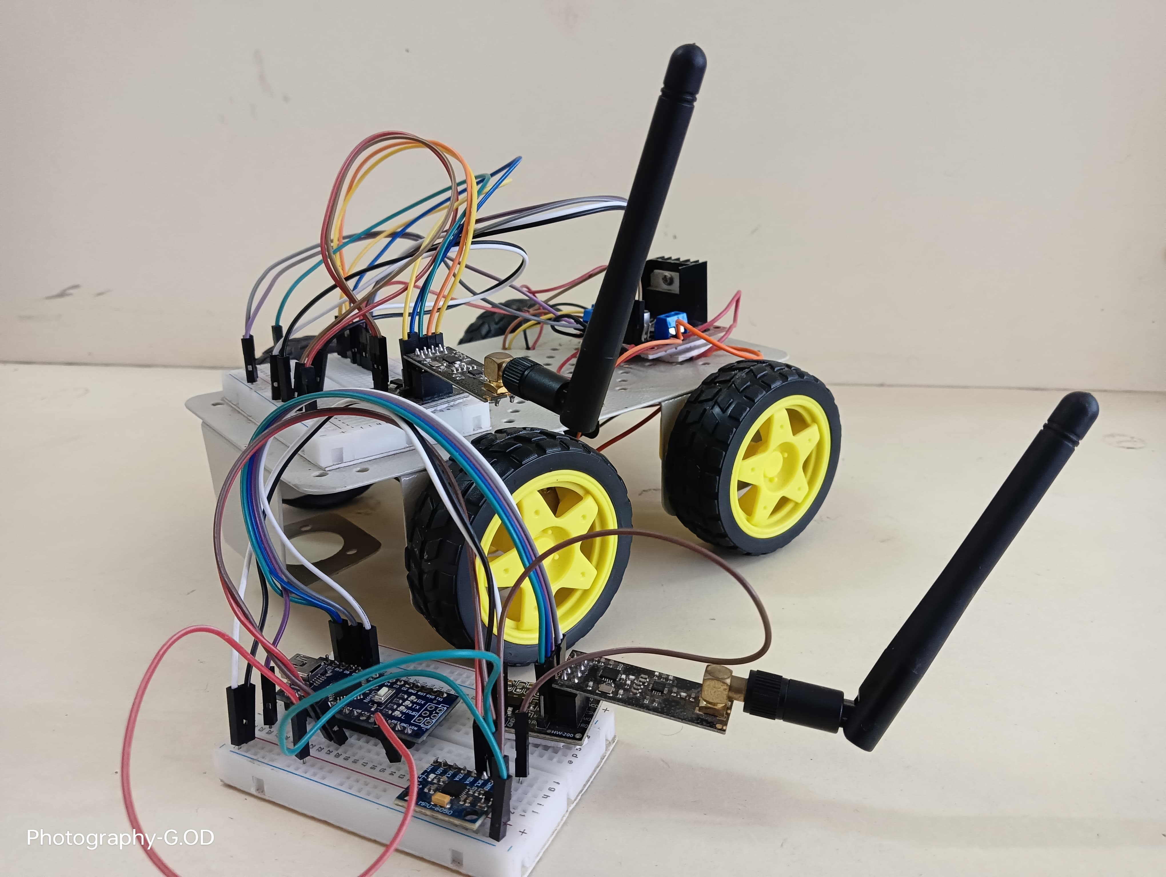
Project Overview
A robot that interprets and responds to human hand gestures, enabling intuitive non-verbal control.
Technical Analysis
Powered by NRC AIAs a robotics and electronics expert, I'm delighted to provide a comprehensive technical analysis for your "Gesture Control Robot" project. This project is an excellent stepping stone for engineering students to understand fundamental concepts in embedded systems, sensor interfacing, motor control, and human-robot interaction.
Gesture Control Robot: Detailed Technical Analysis
article1. Technical Overview
The "Gesture Control Robot" project aims to create a mobile robot that can be intuitively controlled by human hand gestures. The core principle involves capturing the orientation and motion of the user's hand, interpreting these movements as commands, and then translating these commands into corresponding robot actions (e.g., move forward, backward, turn left, turn right, stop).
Here's a breakdown of the technical workflow:
- Gesture Sensing: An Inertial Measurement Unit (IMU) sensor, typically an MPU6050 (which combines a 3-axis accelerometer and a 3-axis gyroscope), is attached to the user's hand or wrist. This sensor continuously measures acceleration and angular velocity along its X, Y, and Z axes.
- Data Acquisition: The microcontroller (e.g., Arduino Uno) communicates with the MPU6050 via the I2C serial communication protocol. It requests and receives raw accelerometer and gyroscope data at regular intervals.
- Data Processing & Fusion (Optional but recommended for robustness):
- Accelerometer Data: Provides information about static orientation (tilt) and linear acceleration. It's good for determining tilt angles, but susceptible to noise from vibrations and linear motion.
- Gyroscope Data: Provides information about angular velocity, useful for detecting rotational movements. It's prone to drift over time (integration errors).
- Sensor Fusion: For more accurate and stable orientation estimation (e.g., pitch and roll angles), a sensor fusion algorithm like a Complementary Filter or Kalman Filter can combine accelerometer and gyroscope data. For this basic project, direct thresholding of processed accelerometer values (pitch/roll derived) will suffice, but it's important to know the limitations.
- Gesture Interpretation: Based on the processed sensor data (e.g., derived pitch and roll angles), the microcontroller applies predefined thresholds to identify specific gestures. For instance:
- Tilting hand forward = Robot moves forward.
- Tilting hand backward = Robot moves backward.
- Tilting hand left = Robot turns left.
- Tilting hand right = Robot turns right.
- Hand flat/neutral = Robot stops.
- Motor Control: Once a gesture is recognized, the microcontroller sends appropriate control signals (HIGH/LOW logic states) to a motor driver module (e.g., L298N H-bridge). The motor driver then translates these signals into the required voltage and current to drive the DC motors on the robot, controlling their direction and speed.
- Robot Actuation: The DC motors, connected to wheels, propel the robot according to the received commands, typically using a differential drive mechanism where independent control of two wheels allows for forward, backward, and turning movements.
This project demonstrates a closed-loop system where sensor input drives actuator output based on programmed logic, forming the foundation of many robotic and control systems.
article2. Components Required
Here's a comprehensive list of components needed for the Gesture Control Robot:
| Category | Component | Quantity | Description |
|---|---|---|---|
| Microcontroller | Arduino Uno (or Nano/Mega) | 1 | The brain of the robot, processes sensor data and controls motors. Arduino Uno is robust and widely supported. |
| Gesture Sensor | MPU6050 Accelerometer & Gyroscope Module | 1 | Captures hand orientation and motion data. Communicates via I2C. |
| Motor Driver | L298N Motor Driver Module | 1 | H-bridge module capable of driving two DC motors bidirectionally. It can handle higher currents than the Arduino's pins. |
| Actuators | DC Gear Motors (BO Motors) | 2 | Small DC motors with reduction gears, providing sufficient torque for the robot to move. BO (Battery Operated) motors are common. |
| Robot Chassis | 2-Wheel Robot Chassis Kit | 1 | A basic two-wheel drive chassis with mounting points for motors, wheels, and electronics. Often includes a caster wheel. |
| Wheels | Robot Wheels (to fit motors) | 2 | Typically plastic or rubber wheels that attach to the motor shafts. |
| Support | Caster Wheel | 1 | Provides stability and allows for easy turning, acting as a third point of contact. Usually included in chassis kits. |
| Power Supply | 9V Battery (or 4-6x AA/AAA batteries) | 1 | For powering the Arduino (via VIN or barrel jack) and the motor driver (separate input for motors). A single higher capacity 7.4V LiPo battery is also a good option if using a suitable regulator. |
| 9V Battery Snap Connector | 1 | For 9V battery. | |
| Connectivity | Jumper Wires (Male-to-Male, Male-to-Female) | ~40-50 | Essential for connecting components on the breadboard and to the Arduino/motor driver. |
| Prototyping | Small Breadboard (optional) | 1 | Useful for clean wiring of the MPU6050 module or power distribution if needed. |
| Miscellaneous | USB-B Cable | 1 | To upload code to the Arduino Uno. |
| Small Velcro Straps or Rubber Bands | A few | For attaching the MPU6050 to the user's hand/wrist. | |
| Screws & Nuts | As needed | For assembling the chassis and mounting components. (Usually included with chassis kit) | |
| Small Screwdriver | 1 | For assembly. |
article3. Circuit Diagram Description
This section describes the wiring connections for the project. Assume an Arduino Uno for pin definitions.
General Wiring Principles:
- Power: Ensure all components share a common ground (GND). Use separate power sources for the Arduino (5V logic, its own regulator) and the motors (higher current, usually 6-12V, directly to L298N).
- Motor Driver (L298N): The L298N requires two separate power inputs: one for its internal logic (typically 5V, usually from Arduino's 5V pin) and one for the motors (typically 6-12V, directly from the battery pack). It has several input pins for controlling motor direction and speed (via Enable pins, if used).
- MPU6050 (I2C): This sensor communicates via I2C (Inter-Integrated Circuit) protocol, which uses two wires: SDA (Serial Data Line) and SCL (Serial Clock Line). Arduino Uno's SDA is A4 and SCL is A5.
Detailed Connections:
label_importantA. Arduino Uno Power
- Connect the 9V battery snap to the Arduino Uno's barrel jack, or connect the battery's positive (+) to and negative (-) to
VIN.GND- Alternatively, you can power the Arduino directly from the USB cable during development.
label_importantB. MPU6050 Sensor Module to Arduino Uno
The MPU6050 typically comes as a module with 4 to 8 pins. Focus on the VCC, GND, SDA, and SCL pins.
- MPU6050 VCC $\rightarrow$ Arduino 5V
- MPU6050 GND $\rightarrow$ Arduino GND
- MPU6050 SDA $\rightarrow$ Arduino A4 (Analog Pin 4, used for I2C Data)
- MPU6050 SCL $\rightarrow$ Arduino A5 (Analog Pin 5, used for I2C Clock)
label_importantC. L298N Motor Driver Module to Arduino Uno & Motors
The L298N module has multiple screw terminals and pin headers.
-
L298N Power (Motor Supply):
- Connect the positive (+) terminal of your motor battery pack (e.g., 6V from 4xAA batteries) to the L298N's or
+12Vscrew terminal (often labelled for 5-35V input).VCC - Connect the negative (-) terminal of the motor battery pack to the L298N's screw terminal.
GND - Crucially: Connect the L298N's to one of the Arduino's
GNDpins to establish a common ground for logic and motor power.GND
- Connect the positive (+) terminal of your motor battery pack (e.g., 6V from 4xAA batteries) to the L298N's
-
L298N Logic Power:
- Most L298N modules have a 5V regulator built-in. If there's a jumper on (or similar), ensure it's in place. If not, or if you prefer external supply, connect L298N's
EN5Vpin (often next to GND on the screw terminal block) to the Arduino's5Vpin. This provides power for the L298N's internal logic.5V
- Most L298N modules have a 5V regulator built-in. If there's a jumper on
-
L298N Control Pins to Arduino Digital Pins:
- Motor 1 (Right Motor):
- L298N $\rightarrow$ Arduino Digital Pin 2
IN1 - L298N $\rightarrow$ Arduino Digital Pin 3
IN2 - (Optional) L298N $\rightarrow$ Arduino Digital Pin 9 (PWM) (If using speed control; if not, connect
ENAdirectly to L298N'sENAor5Vlogic to enable it).VCC
- L298N
- Motor 2 (Left Motor):
- L298N $\rightarrow$ Arduino Digital Pin 4
IN3 - L298N $\rightarrow$ Arduino Digital Pin 5
IN4 - (Optional) L298N $\rightarrow$ Arduino Digital Pin 10 (PWM) (If using speed control; if not, connect
ENBdirectly to L298N'sENBor5Vlogic to enable it).VCC
- L298N
- Motor 1 (Right Motor):
-
DC Motors to L298N Output Terminals:
- Right Motor: Connect the two wires of the right DC motor to L298N's and
OUT1screw terminals. The polarity determines initial direction; you can swap them if the motor spins opposite to expectation.OUT2 - Left Motor: Connect the two wires of the left DC motor to L298N's and
OUT3screw terminals.OUT4
- Right Motor: Connect the two wires of the right DC motor to L298N's
Simplified Circuit Diagram Concept:
+-----------------+ | Arduino Uno | | | (Hand/Wrist) +-----------+ | +-------+ | | MPU6050 | I2C | | | | | (VCC, GND,| ----> | A4| SDA | | | SDA, SCL)| | A5| SCL | | +-----------+ | | | | | +-------+ | | | | Digital Pins | | +-------------+| |D2| IN1 || |D3| IN2 || |D4| IN3 || |D5| IN4 || |D9| ENA (PWM) || (Optional for speed) |D10| ENB (PWM) || (Optional for speed) | +-------------+| | | | GND <----------+-----------------+ | | | +-----------------+ | | +-----------------+ | | L298N Motor | | | Driver | | Motor Battery Pack --> +VCC (Motor) | +12V | | (e.g., 6V from 4xAA) | | GND <-----------+-----------------+ | | | --- | IN1 IN2 IN3 IN4 ENA ENB | --- | ^ ^ ^ ^ ^ ^ | | +----|---|---|---|---|---|----------+ | | | | | | | | (Arduino Digital Pins 2,3,4,5,9,10) | | +----------+ +------------------| OUT1 OUT2| <--- Right DC Motor | OUT3 OUT4| <--- Left DC Motor +----------+
Note on L298N ENA/ENB pins:
- If you don't connect and
ENAto PWM pins on the Arduino, you must connect them to the L298N's 5V logic output (or directly to the positive of the logic supply, if separate) to ensure the motors are enabled. For basic on/off control, this is common.ENB - For speed control, connect and
ENAto PWM-capable pins on the Arduino (e.g., D9 and D10 on Uno) and useENBto set speed.analogWrite()
article4. Source Code
This code uses the
MPU6050_tocknProgramming Language: C++ (Arduino Sketch)
C++// 1. Include Libraries #include <Wire.h> // Required for I2C communication with MPU6050 #include <MPU6050_tockn.h> // Library for MPU6050 sensor // 2. Define Pin Assignments // L298N Motor Driver Pins #define ENA_PIN 9 // Enable pin for Motor A (Right Motor) - Connect to PWM pin for speed control #define IN1_PIN 2 // Input 1 for Motor A (Right Motor) #define IN2_PIN 3 // Input 2 for Motor A (Right Motor) #define ENB_PIN 10 // Enable pin for Motor B (Left Motor) - Connect to PWM pin for speed control #define IN3_PIN 4 // Input 1 for Motor B (Left Motor) #define IN4_PIN 5 // Input 2 for Motor B (Left Motor) // 3. Create MPU6050 Object MPU6050 mpu6050(Wire); // Create an MPU6050 object, passing the Wire library instance // 4. Global Variables for Gesture Control // Define thresholds for gesture recognition (these will need calibration) // Accelerometer values are typically around +/- 16384 for +/- 2g range // Pitch and Roll angles range from -90 to 90 degrees. const float FORWARD_THRESHOLD = -20.0; // Tilt hand forward (pitch angle) const float BACKWARD_THRESHOLD = 20.0; // Tilt hand backward (pitch angle) const float LEFT_THRESHOLD = 20.0; // Tilt hand left (roll angle) const float RIGHT_THRESHOLD = -20.0; // Tilt hand right (roll angle) const float STOP_TOLERANCE = 10.0; // Angle range around zero for stopping // Motor speed (0-255 for PWM) const int motorSpeed = 150; // Adjust for desired robot speed // 5. Function Prototypes (Good practice for larger projects) void moveRobot(int rightMotorDir, int leftMotorDir, int speed); void stopRobot(); void moveForward(); void moveBackward(); void turnLeft(); void turnRight(); // --- SETUP FUNCTION --- void setup() { Serial.begin(9600); // Initialize serial communication for debugging // Initialize I2C communication Wire.begin(); // Initialize MPU6050 sensor mpu6050.begin(); // Calibrate MPU6050 (optional but recommended for accuracy) // This helps compensate for sensor offset. Keep the sensor still during calibration. Serial.println("Calibrating MPU6050. Please keep the sensor still..."); mpu6050.calcOffsets(true,true); // Calibrate gyro and accel offsets Serial.println("Calibration complete."); // Configure Motor Driver Pins as Outputs pinMode(ENA_PIN, OUTPUT); pinMode(IN1_PIN, OUTPUT); pinMode(IN2_PIN, OUTPUT); pinMode(ENB_PIN, OUTPUT); pinMode(IN3_PIN, OUTPUT); pinMode(IN4_PIN, OUTPUT); // Initially stop the robot stopRobot(); } // --- LOOP FUNCTION --- void loop() { // Update MPU6050 data mpu6050.update(); // Get Pitch and Roll angles from MPU6050 // Pitch is rotation around X-axis (forward/backward tilt) // Roll is rotation around Y-axis (left/right tilt) float pitch = mpu6050.getAngleX(); // Or getAngleY(), depending on sensor orientation on hand float roll = mpu6050.getAngleY(); // Or getAngleX(), depending on sensor orientation on hand // Print angles for debugging and calibration Serial.print("Pitch: "); Serial.print(pitch); Serial.print("\tRoll: "); Serial.println(roll); // Gesture Interpretation Logic // Check for forward/backward tilt (Pitch) if (pitch < FORWARD_THRESHOLD) { moveForward(); Serial.println("Moving Forward"); } else if (pitch > BACKWARD_THRESHOLD) { moveBackward(); Serial.println("Moving Backward"); } // Check for left/right tilt (Roll) else if (roll > LEFT_THRESHOLD) { turnLeft(); Serial.println("Turning Left"); } else if (roll < RIGHT_THRESHOLD) { turnRight(); Serial.println("Turning Right"); } // If no significant tilt, stop else if (abs(pitch) < STOP_TOLERANCE && abs(roll) < STOP_TOLERANCE) { stopRobot(); Serial.println("Stopped"); } delay(50); // Small delay to prevent reading too fast and allow time for movement } // --- HELPER FUNCTIONS FOR ROBOT MOVEMENT --- /** * Controls the direction and speed of both motors. * @param rightMotorDir Direction for the right motor (e.g., HIGH for forward, LOW for backward) * @param leftMotorDir Direction for the left motor (e.g., HIGH for forward, LOW for backward) * @param speed PWM speed value (0-255) */ void moveRobot(int rightMotorDir, int leftMotorDir, int speed) { // Right Motor (Motor A) // Direction depends on IN1 and IN2 state digitalWrite(IN1_PIN, rightMotorDir == HIGH ? LOW : HIGH); // Adjust HIGH/LOW based on your motor wiring and desired direction digitalWrite(IN2_PIN, rightMotorDir == HIGH ? HIGH : LOW); // You might need to swap these for your motors analogWrite(ENA_PIN, speed); // Set speed for Right Motor // Left Motor (Motor B) // Direction depends on IN3 and IN4 state digitalWrite(IN3_PIN, leftMotorDir == HIGH ? HIGH : LOW); // Adjust HIGH/LOW based on your motor wiring and desired direction digitalWrite(IN4_PIN, leftMotorDir == HIGH ? LOW : HIGH); // You might need to swap these for your motors analogWrite(ENB_PIN, speed); // Set speed for Left Motor } /** * Stops both motors by setting their enable pins to 0. */ void stopRobot() { analogWrite(ENA_PIN, 0); // Stop Right Motor analogWrite(ENB_PIN, 0); // Stop Left Motor // Alternatively, you can also set INx pins to LOW or to the same state // digitalWrite(IN1_PIN, LOW); // digitalWrite(IN2_PIN, LOW); // digitalWrite(IN3_PIN, LOW); // digitalWrite(IN4_PIN, LOW); } /** * Moves the robot forward. * Both motors spin in the same forward direction. */ void moveForward() { // Assuming HIGH for forward direction (adjust based on your wiring) moveRobot(HIGH, HIGH, motorSpeed); } /** * Moves the robot backward. * Both motors spin in the same backward direction. */ void moveBackward() { // Assuming LOW for backward direction (adjust based on your wiring) moveRobot(LOW, LOW, motorSpeed); } /** * Turns the robot left. * Right motor forward, Left motor backward (or stopped) for pivot turn. */ void turnLeft() { // Right motor forward, Left motor backward (or slower/stopped) // For a precise turn, one motor might need to go backward while the other goes forward // Or one motor runs at full speed and the other at half speed. // Example: right motor forward, left motor backward for pivot turn digitalWrite(IN1_PIN, LOW); // Right motor backward signal digitalWrite(IN2_PIN, HIGH); analogWrite(ENA_PIN, motorSpeed); digitalWrite(IN3_PIN, LOW); // Left motor forward signal digitalWrite(IN4_PIN, HIGH); analogWrite(ENB_PIN, motorSpeed); } /** * Turns the robot right. * Left motor forward, Right motor backward (or stopped) for pivot turn. */ void turnRight() { // Left motor forward, Right motor backward (or slower/stopped) digitalWrite(IN1_PIN, HIGH); // Right motor forward signal digitalWrite(IN2_PIN, LOW); analogWrite(ENA_PIN, motorSpeed); digitalWrite(IN3_PIN, HIGH); // Left motor backward signal digitalWrite(IN4_PIN, LOW); analogWrite(ENB_PIN, motorSpeed); }
Important Notes for moveRobotturnLeftturnRight
- The and
HIGHvalues forLOW/IN1_PINandIN2_PIN/IN3_PINdetermine the direction of the motors. You will likely need to adjust these based on how you've wired your motors to the L298N outputs and which way your physical motors spin. For example, ifIN4_PINmakes the motor spin one way, then swapping them (digitalWrite(IN1_PIN, HIGH); digitalWrite(IN2_PIN, LOW);) will make it spin the other way. Test your individual motors first!digitalWrite(IN1_PIN, LOW); digitalWrite(IN2_PIN, HIGH); - The and
turnLeft()functions implement a "pivot turn" by making one wheel spin forward and the other spin backward. For a "swing turn", one wheel can spin forward while the other is stopped or spins very slowly. Experiment to find what works best for your robot's stability and maneuverability.turnRight()
article5. Source Code Structure
The source code is structured to be modular and easy to understand for educational purposes.
-
Main Modules:
- Initialization (): Handles setting up serial communication, initializing the I2C bus, configuring the MPU6050 sensor (including optional calibration), and setting up motor control pins as outputs.
setup() - Main Loop (): This is the heart of the program. It continuously reads sensor data, interprets gestures, and commands the robot accordingly.
loop() - Sensor Data Acquisition: Reads raw accelerometer and gyroscope data from the MPU6050 and processes it (the library handles much of the raw data processing and angle calculation internally).
MPU6050_tockn - Gesture Recognition Logic: Compares the derived pitch and roll angles against predefined thresholds to determine the intended gesture (forward, backward, left, right, stop).
- Motor Control Logic: Translates the recognized gesture into specific commands for the motor driver to control the direction and speed of the robot's wheels.
- Initialization (
-
Libraries Needed:
- : Standard Arduino library for I2C (Two-Wire Interface) communication. Essential for communicating with the MPU6050.
Wire.h - : A popular Arduino library for the MPU6050 sensor that simplifies reading accelerometer, gyroscope, and calculated angle data. It's available through the Arduino IDE's Library Manager.
MPU6050_tockn.h
-
Key Functions:
- : Runs once when the Arduino starts. Configures pins, initializes sensors and serial communication.
setup() - : Runs repeatedly after
loop(). Contains the main logic for reading sensor data, processing it, and controlling the robot.setup() - : Initializes the MPU6050 sensor and checks for its presence.
mpu6050.begin() - : Reads new data from the MPU6050 sensor.
mpu6050.update() - ,
mpu6050.getAngleX(): Returns the calculated Pitch (X-axis rotation) and Roll (Y-axis rotation) angles respectively.mpu6050.getAngleY() - : A general-purpose function to control both motors with specified direction and speed.
moveRobot(int rightMotorDir, int leftMotorDir, int speed) - : Stops both motors by setting their speed to zero.
stopRobot() - ,
moveForward(),moveBackward(),turnLeft(): Wrapper functions that callturnRight()or directly control the motors for specific robot movements, making themoveRobot()function more readable.loop()
article6. Step-by-Step Implementation Guide
Follow these steps carefully to build and program your Gesture Control Robot.
label_importantA. Hardware Assembly Steps
- Chassis Assembly:
- Assemble the robot chassis according to its instructions. This usually involves attaching the bottom plate, side plates, and any standoffs.
- Mount the DC gear motors to the chassis using the provided brackets and screws. Ensure they are securely fastened.
- Attach the wheels to the motor shafts. Push them firmly until they click into place.
- Attach the caster wheel (the omnidirectional wheel) to the appropriate location on the chassis.
- Mounting Electronics:
- Mount the Arduino Uno board onto the chassis using standoffs and screws.
- Mount the L298N motor driver module next to the Arduino, ensuring easy access to its terminals.
- Mount the battery holder/pack securely to the chassis.
- Wiring the Motors:
- Connect the two wires from the Right Motor to the OUT1 and OUT2 screw terminals on the L298N.
- Connect the two wires from the Left Motor to the OUT3 and OUT4 screw terminals on the L298N.
- Self-correction tip: If a motor spins backward when it should go forward, simply swap the two wires connected to its respective OUT terminals on the L298N.
- Wiring the Power Supply:
- Connect the positive (+) terminal of your motor battery pack (e.g., 6V) to the or
+12Vinput terminal on the L298N.VCC - Connect the negative (-) terminal of the motor battery pack to the terminal on the L298N.
GND - Connect the Arduino's 9V battery snap to the Arduino's barrel jack (or VIN/GND pins).
- Crucial: Connect the terminal of the L298N to any
GNDpin on the Arduino Uno. This ensures a common ground for all components.GND - If your L298N module has an jumper, ensure it's in place. If it has a separate
EN5Vlogic input, connect it to the Arduino's5Vpin.5V
- Connect the positive (+) terminal of your motor battery pack (e.g., 6V) to the
- Wiring the Motor Driver Control Signals:
- L298N $\rightarrow$ Arduino Digital Pin 2
IN1 - L298N $\rightarrow$ Arduino Digital Pin 3
IN2 - L298N $\rightarrow$ Arduino Digital Pin 4
IN3 - L298N $\rightarrow$ Arduino Digital Pin 5
IN4 - L298N $\rightarrow$ Arduino Digital Pin 9 (PWM)
ENA - L298N $\rightarrow$ Arduino Digital Pin 10 (PWM)
ENB
- L298N
- Wiring the MPU6050 Sensor:
- MPU6050 $\rightarrow$ Arduino
VCC5V - MPU6050 $\rightarrow$ Arduino
GNDGND - MPU6050 $\rightarrow$ Arduino
SDAA4 - MPU6050 $\rightarrow$ Arduino
SCLA5
- MPU6050
- Final Checks: Double-check all connections for proper polarity and pin assignments before applying power. Loose connections can lead to unexpected behavior or component damage.
label_importantB. Software Setup and Programming
- Install Arduino IDE: If you don't have it, download and install the Arduino IDE from the official Arduino website.
- Install MPU6050_tockn Library:
- Open Arduino IDE.
- Go to .
Sketch > Include Library > Manage Libraries... - In the Library Manager, search for "MPU6050_tockn".
- Click "Install" for the library by "tockn".
- Load the Source Code:
- Copy the provided source code into a new Arduino sketch ().
File > New - Save the sketch ().
File > Save As...
- Copy the provided source code into a new Arduino sketch (
- Select Board and Port:
- Go to and select "Arduino Uno" (or your specific Arduino board).
Tools > Board - Go to and select the serial port corresponding to your Arduino.
Tools > Port
- Go to
- Upload Code:
- Connect your Arduino Uno to your computer via the USB cable.
- Click the "Upload" button (right arrow icon) in the Arduino IDE. The code will compile and then be uploaded to your Arduino.
- Monitor the output window at the bottom of the IDE for any compilation or upload errors.
label_importantC. Testing and Calibration Procedures
- MPU6050 Sensor Data Verification:
- After uploading the code, open the Serial Monitor ().
Tools > Serial Monitor - Set the baud rate to .
9600 - You should see continuous readings of "Pitch:" and "Roll:" angles.
- Hold the MPU6050 sensor flat (e.g., on a table). The Pitch and Roll values should be close to 0.
- Tilt the sensor forward: Pitch should become negative.
- Tilt the sensor backward: Pitch should become positive.
- Tilt the sensor left: Roll should become positive.
- Tilt the sensor right: Roll should become negative.
- This confirms the sensor is working and providing correct orientation data. If values are noisy or not stable, ensure sensor is placed firmly and away from vibrating components.
- After uploading the code, open the Serial Monitor (
- Calibrating Gesture Thresholds:
- The ,
FORWARD_THRESHOLD,BACKWARD_THRESHOLD,LEFT_THRESHOLD, andRIGHT_THRESHOLDconstants in the code are critical.STOP_TOLERANCE - While watching the Serial Monitor, perform each gesture (tilt forward, backward, left, right, hold flat) and note down the typical Pitch and Roll values for each.
- Adjust the threshold values in the code based on your observations. For instance, if you want the robot to move forward when you tilt your hand forward by about 15 degrees, set to
FORWARD_THRESHOLD(since forward tilt typically results in negative pitch).-15.0 - Upload the code after each threshold adjustment and re-test. This is an iterative process.
- The
- Motor Direction and Speed Test:
- Hold the robot off the ground or place it on a stand so the wheels can spin freely.
- Perform a gesture (e.g., tilt forward). Observe if the motors spin in the correct direction to move the robot forward.
- If a motor spins backward for a given command (e.g., during ), you need to adjust the
moveForward()/HIGHstates forLOWin theINx_PINfunction specifically for that motor.moveRobot() - Adjust (0-255) to achieve desired robot speed. A higher value makes it faster.
motorSpeed - Test and
turnLeft()to ensure the robot turns as expected. If it pivots awkwardly, you may need to adjust the motor directions within those functions or even the speed of one motor relative to the other.turnRight()
- Full System Test:
- Place the robot on the ground.
- Strap the MPU6050 module to your hand/wrist.
- Perform gestures and observe the robot's response.
- Refine the gesture thresholds and motor control parameters until the robot responds reliably and smoothly to your commands.
article7. Challenges and Solutions
Students may encounter several challenges during this project. Here are common ones and their solutions:
-
Challenge: MPU6050 Data Noise and Drift
- Problem: Raw accelerometer data can be noisy due to vibrations. Gyroscope data drifts over time, leading to inaccurate angle estimations. This results in unstable gesture recognition.
- Solution:
- Sensor Fusion: Implement a Complementary Filter or Kalman Filter (more complex) to combine accelerometer and gyroscope data for more stable angle estimation. The library already provides fused angles, which helps significantly.
MPU6050_tockn - Physical Stability: Mount the MPU6050 firmly on the hand/wrist. Avoid excessive vibrations.
- Averaging: Take multiple readings and average them to smooth out momentary spikes.
- Calibration: Run in
mpu6050.calcOffsets(true,true);to compensate for sensor biases. Keep the sensor absolutely still during calibration.setup()
- Sensor Fusion: Implement a Complementary Filter or Kalman Filter (more complex) to combine accelerometer and gyroscope data for more stable angle estimation. The
-
Challenge: Inconsistent Gesture Recognition
- Problem: The robot performs the wrong action or no action despite the correct hand gesture.
- Solution:
- Threshold Calibration: This is the most common issue. Use the Serial Monitor to observe Pitch/Roll values for each desired gesture. Adjust the constants in the code incrementally until responses are reliable. Consider adding a small "dead zone" (e.g., using
*_THRESHOLD) around the neutral position to prevent accidental movements.STOP_TOLERANCE - Gesture Definition: Ensure the gestures are distinct enough (e.g., a clear tilt forward, not just a slight lean).
- User Consistency: Train the user to perform gestures consistently.
- Threshold Calibration: This is the most common issue. Use the Serial Monitor to observe Pitch/Roll values for each desired gesture. Adjust the
-
Challenge: Motors Not Spinning or Spinning Incorrectly
- Problem: Motors don't respond, or spin in the wrong direction/at incorrect speeds.
- Solution:
- Power: Check battery levels for both the Arduino and the motor driver. Ensure the L298N's (motor power) and
+12V(logic power) inputs are correctly connected and receiving sufficient voltage.5V - Common Ground: Verify that the of the L298N is connected to the
GNDof the Arduino. Without a common ground, control signals won't be interpreted correctly.GND - Wiring: Double-check all and
INx_PINconnections from Arduino to L298N. Ensure motor wires are connected toENx_PINterminals.OUTx - Code Logic: In the function, swap
moveRobot()/HIGHforLOWif a motor spins backward unexpectedly.digitalWrite(INx_PIN, ...) - ENA/ENB: If not using PWM for speed control, ensure and
ENApins on the L298N are connected to the L298N's 5V logic (or directly to VCC if it applies). If using PWM, ensure you're usingENBand the pin is PWM capable.analogWrite()
- Power: Check battery levels for both the Arduino and the motor driver. Ensure the L298N's
-
Challenge: Motor Interference / Electrical Noise
- Problem: Motors cause glitches, freezes, or erratic behavior in the Arduino or sensor readings.
- Solution:
- Separate Power Supplies: Use completely separate batteries for the Arduino (and MPU6050) and the motors (via L298N). Only share a common ground.
- Capacitors: Solder small capacitors (e.g., 0.1uF ceramic in parallel with 100uF electrolytic) across the terminals of each DC motor to suppress electrical noise generated by the motor brushes.
- Wire Routing: Keep motor wires away from sensor and communication (I2C) wires.
- Ferrite Beads: Place ferrite beads on motor power lines to reduce EMI.
-
Challenge: Debugging Issues
- Problem: Code compiles, but robot doesn't behave as expected, and it's hard to find the source of the problem.
- Solution:
- Serial Debugging: Use extensively to output variable values (like Pitch, Roll, motor states, recognized gesture) at different points in your code. This helps trace program flow and pinpoint where values deviate from expectations.
Serial.print() - Modular Testing: Test components individually (e.g., first ensure MPU6050 data is read correctly, then test motor control with simple commands, then combine).
- Simplify: Temporarily comment out complex parts of the code to isolate issues.
- Serial Debugging: Use
article8. Learning Outcomes
This project offers a rich learning experience for engineering students, covering several core concepts:
- Microcontroller Programming: Students will gain hands-on experience with Arduino IDE and C++ programming for embedded systems, including control flow, functions, and variable management.
- Sensor Interfacing (I2C Communication): Understanding how to connect and communicate with digital sensors using protocols like I2C (demonstrated with MPU6050). This involves reading datasheets, understanding registers, or using libraries that abstract these details.
- Motor Control: Learning how to drive DC motors bidirectionally and control their speed using an H-bridge motor driver (L298N) and Pulse Width Modulation (PWM) signals from the microcontroller.
- Basic Signal Processing: Understanding how to acquire raw sensor data and apply simple processing (e.g., thresholding, basic angle calculation via library) to derive meaningful information.
- Introduction to Robotics Kinematics: Grasping the basics of a differential drive robot (how independent motor control leads to linear and rotational movement).
- System Integration: Combining hardware components (sensors, actuators, power, microcontroller) with software logic to create a functional system. This is a critical skill in robotics.
- Debugging and Troubleshooting: Developing systematic approaches to identify and resolve hardware and software issues, a fundamental skill for any engineer.
- Project Management: Experience the full cycle of a small engineering project, from conceptualization and component selection to assembly, programming, testing, and refinement.
- Human-Robot Interaction (HRI) Fundamentals: Understanding a basic form of non-verbal HRI through gesture recognition.
article9. Extensions and Improvements
Once the basic gesture control robot is functional, there are numerous ways to enhance its capabilities and complexity:
-
Wireless Control:
- Bluetooth (HC-05/06): Control the robot from a smartphone app or another Arduino with an IMU, enabling true remote gesture control.
- RF Modules (NRF24L01): For more robust, low-power, and longer-range wireless communication between a gesture-sensing unit and the robot.
- Wi-Fi (ESP8266/ESP32): Integrate Wi-Fi for web-based control interfaces or IoT capabilities.
-
Advanced Gesture Recognition:
- Sensor Fusion Algorithms: Implement a full Complementary Filter or Kalman Filter from scratch to improve the accuracy and stability of orientation estimates, reducing drift.
- Machine Learning (TinyML): Collect a dataset of various gestures and train a small neural network (e.g., using TensorFlow Lite for Microcontrollers on an ESP32 or similar capable MCU) to recognize more complex, natural gestures.
- Dynamic Time Warping (DTW): A classical algorithm for comparing time series data, useful for recognizing gestures that vary in speed or duration.
- More Gestures: Expand the gesture vocabulary beyond basic movements (e.g., specific handshakes for actions, wave for emergency stop).
-
Improved Robot Navigation & Autonomy:
- Obstacle Avoidance: Add ultrasonic (HC-SR04) or infrared (IR) distance sensors to enable the robot to detect and avoid obstacles autonomously.
- Line Following: Implement IR line follower sensors to allow the robot to follow a predefined path.
- Odometry: Add encoders to the motors to measure wheel rotations, allowing the robot to estimate its position and travel precise distances.
- PID Control: Implement PID controllers for motor speed and direction for smoother and more accurate movements, especially for maintaining a straight line or precise turns.
-
Feedback Systems:
- Visual Feedback: Add RGB LEDs to indicate robot status (e.g., red for stop, green for moving, blue for turning).
- Auditory Feedback: Integrate a buzzer or small speaker for sound cues (e.g., "beep" when a command is received, warning sounds).
- LCD Display: Add a small LCD (e.g., 16x2 I2C LCD) to display sensor values, robot status, or current command.
-
Enhanced Robot Design:
- Mecanum Wheels: Explore Mecanum wheels for omnidirectional movement, allowing the robot to move sideways without turning.
- Robot Arm Integration: Add a small robotic arm that can be controlled by specific hand gestures, enabling manipulation tasks.
- Tracked Robot: Design a tracked robot for improved traction on varied terrain.
-
Power Management:
- Implement power-saving modes for the microcontroller and sensors when the robot is idle to extend battery life.
- Explore more efficient motor drivers (e.g., DRV8833 or A4988) for better power consumption.
-
ROS Integration: For advanced students, integrate the Arduino with a Robot Operating System (ROS) environment running on a Raspberry Pi (mounted on the robot). This allows for modular development, advanced navigation stacks, and simulation capabilities.
By tackling these extensions, students can delve deeper into various subfields of robotics and develop more sophisticated and capable systems. Good luck with your project!
infoThis analysis is generated by AI and should be used as a learning guide. Always verify technical details.