


Obstacle Avoidance Robot
Obstacle Avoidance Robot is an autonomous engineering project developed by the NIST Robotics Club (NRC) at NIST University, Berhampur. An autonomous robot equipped with sensors to detect and navigate around obstacles in its path.

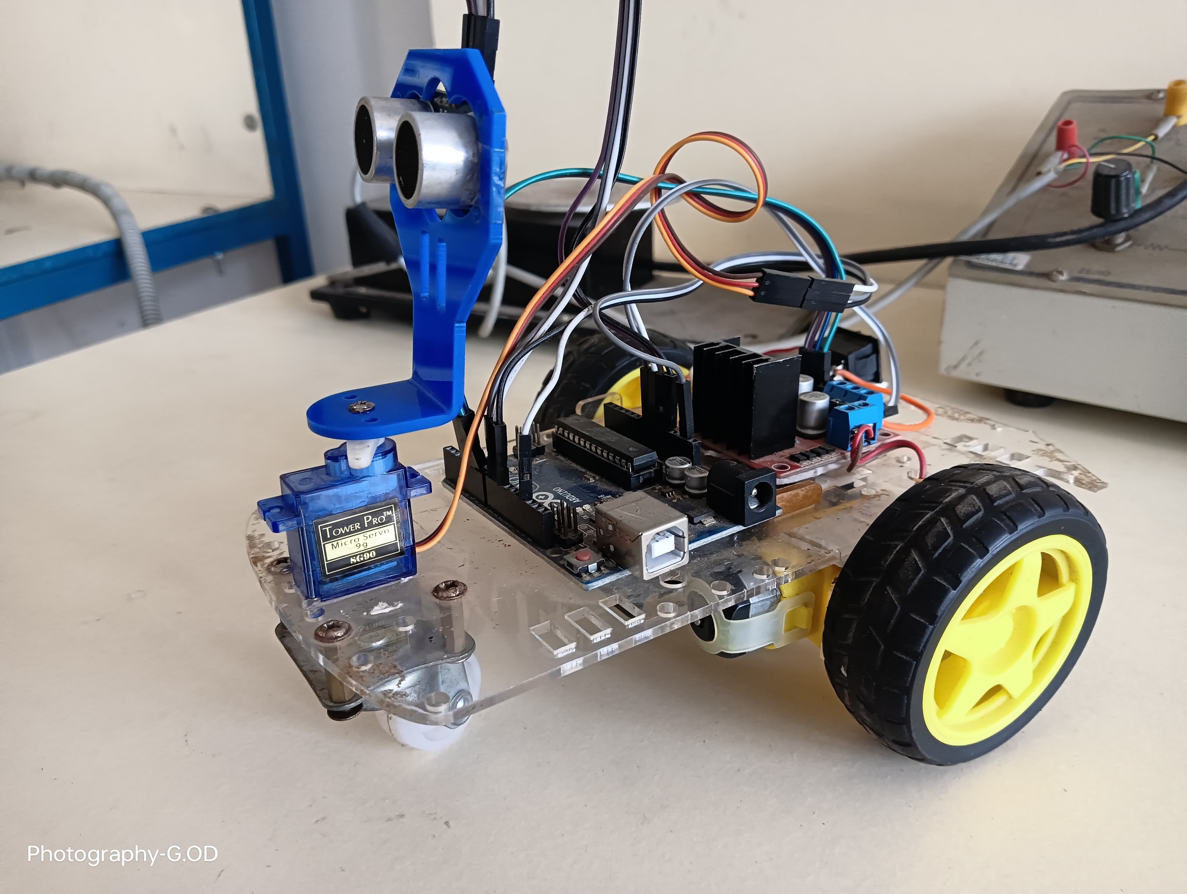
Project Overview
An autonomous robot equipped with sensors to detect and navigate around obstacles in its path.
Technical Analysis
Powered by NRC AIAs a robotics and electronics expert, I'm delighted to provide a detailed technical analysis for the "Obstacle Avoidance Robot" project. This project is fundamental for understanding basic robotics principles and is an excellent starting point for engineering students.
Obstacle Avoidance Robot: A Detailed Technical Analysis
article1. Technical Overview
The Obstacle Avoidance Robot is a classic example of a reactive robotic system. Its core functionality revolves around sensing its environment, processing that information, and reacting accordingly to achieve its goal of navigating without collisions.
How it Works Technically:
-
Sensing (Perception): The robot uses an ultrasonic sensor (HC-SR04) as its primary perception module. This sensor emits high-frequency sound waves (ultrasound) and measures the time it takes for the sound to return after hitting an object. By knowing the speed of sound, the robot can calculate the distance to the object.
- Principle: Time-of-Flight (ToF). The sensor sends a pulse (Trigger) and waits for an echo (Echo). . The division by 2 is because the sound travels to the object and back.
Distance = (Time_taken * Speed_of_sound) / 2
- Principle: Time-of-Flight (ToF). The sensor sends a pulse (Trigger) and waits for an echo (Echo).
-
Processing (Cognition): An Arduino Uno microcontroller acts as the robot's "brain." It continuously reads the distance data from the ultrasonic sensor.
- Decision Logic: Based on a predefined threshold distance, the Arduino makes decisions:
- If the detected distance to an obstacle is below the threshold, the robot decides it needs to avoid the obstacle. It then executes a predefined avoidance maneuver (e.g., stop, turn right, then move forward).
- If the detected distance is above the threshold, or no obstacle is detected, the robot continues to move straight.
- Decision Logic: Based on a predefined threshold distance, the Arduino makes decisions:
-
Actuation (Action): The robot's movement is controlled by two DC gear motors, one for each wheel. To control the motors, a motor driver module (L298N) is essential.
- Motor Driver Role: Microcontrollers typically cannot supply enough current or voltage to directly drive motors. The L298N acts as an H-bridge, allowing the Arduino to control the direction (forward/backward) and speed (via PWM if enabled) of the motors by simply sending low-power digital signals.
- Locomotion: By controlling the direction of each motor independently, the robot can achieve various movements:
- Move Forward: Both motors move forward.
- Turn Right: Left motor moves forward, Right motor stops or moves backward (differential drive).
- Turn Left: Right motor moves forward, Left motor stops or moves backward.
- Stop: Both motors stop.
-
Power Supply: Separate power sources are often used for the microcontroller (e.g., 9V battery or USB) and the motors (e.g., 4xAA battery pack) to ensure stable operation and prevent motor noise/current draw from affecting the microcontroller.
In essence, the project demonstrates a closed-loop control system where sensor input drives actuator output based on programmed logic.
article2. Components Required
Here's a comprehensive list of components for building an Obstacle Avoidance Robot:
-
Microcontroller:
- Arduino Uno R3: The primary control unit. Easy to program and interface with.
-
Sensors:
- HC-SR04 Ultrasonic Sensor: For distance measurement and obstacle detection.
-
Actuators:
- 2x DC Gear Motors (BO Motors): Typically 150-300 RPM, 3-9V operation. These are used for driving the wheels.
- L298N Motor Driver Module: To interface the Arduino with the DC motors. It can control two motors.
-
Chassis & Mobility:
- 2-Wheel Drive Robot Chassis Kit: Includes the base plate, motor mounting brackets, and sometimes wheels.
- 2x Robot Wheels: To be mounted on the DC motors.
- 1x Caster Wheel / Ball Caster: For third-point support and stability, allowing easy turning.
-
Power Supply:
- 1x 9V Battery (with Snap Connector): For powering the Arduino Uno.
- 1x AA Battery Holder (4xAA cells): For powering the DC motors via the L298N. (Requires 4x 1.5V AA batteries, totaling 6V).
- 8x AA Batteries (or Rechargeable AA batteries): For the motor power supply.
-
Connecting Wires:
- Jumper Wires (Male-to-Male, Male-to-Female): Various lengths and colors for making connections between components. A pack with assorted types is recommended.
-
Tools & Miscellaneous:
- Small Screwdriver Set: For assembling the chassis and tightening terminals on the motor driver.
- USB A-B Cable: To connect Arduino Uno to your computer for programming.
- Zip Ties or Double-Sided Tape: For securing components to the chassis.
article3. Circuit Diagram Description
This section describes the connections between the components, assuming an Arduino Uno, HC-SR04, and L298N motor driver.
Pin Configurations and Wiring Details:
-
Arduino Uno Power:
- Connect the 9V battery snap to the DC Jack of the Arduino Uno. Alternatively, connect the battery's positive to Arduino's pin and negative to
VIN.GND
- Connect the 9V battery snap to the DC Jack of the Arduino Uno. Alternatively, connect the battery's positive to Arduino's
-
HC-SR04 Ultrasonic Sensor:
- pin of HC-SR04 $\rightarrow$
VCCpin of Arduino Uno5V - pin of HC-SR04 $\rightarrow$
GNDpin of Arduino UnoGND - pin of HC-SR04 $\rightarrow$ Arduino Digital Pin
Trig9 - pin of HC-SR04 $\rightarrow$ Arduino Digital Pin
Echo10
-
L298N Motor Driver Module:
- Power Input (Motor Supply):
- (or
+12V) terminal on L298N $\rightarrow$ Positive (+) terminal of the 4xAA battery pack (6V).+VCC - terminal on L298N $\rightarrow$ Negative (-) terminal of the 4xAA battery pack.
GND - Important: Also connect L298N's to Arduino's
GNDto establish a common ground for signal reference.GND
- Motor Control Pins (Inputs from Arduino):
- (Input 1 for Motor A) $\rightarrow$ Arduino Digital Pin
IN15 - (Input 2 for Motor A) $\rightarrow$ Arduino Digital Pin
IN24 - (Input 3 for Motor B) $\rightarrow$ Arduino Digital Pin
IN33 - (Input 4 for Motor B) $\rightarrow$ Arduino Digital Pin
IN42 - (Enable for Motor A) $\rightarrow$ Arduino Digital Pin
ENA(Connect to6for full speed, or a PWM pin for speed control). For simplicity, connect directly to Arduino'sHIGHif not using PWM. Correction: It's better to connect to a digital pin so the Arduino can enable/disable the motor driver gates. If not using PWM, just set the pin HIGH. Let's use digital pin 6 and 7 for ENA/ENB and set them HIGH.5V - (Enable for Motor B) $\rightarrow$ Arduino Digital Pin
ENB(Connect to7for full speed, or a PWM pin for speed control).HIGH
- Motor Output Pins:
- and
OUT1(Output for Motor A) $\rightarrow$ Terminals of Left Motor (polarity can be swapped if motor runs backward).OUT2 - and
OUT3(Output for Motor B) $\rightarrow$ Terminals of Right Motor (polarity can be swapped if motor runs backward).OUT4
- Power Input (Motor Supply):
Summary of Connections (Arduino Pin Assignment):
| Component | Component Pin | Arduino Pin | Notes |
|---|---|---|---|
| HC-SR04 | VCC | 5V | |
| GND | GND | ||
| Trig | 9 | Output: Sends ultrasonic pulse | |
| Echo | 10 | Input: Receives reflected pulse | |
| L298N | IN1 (Motor A) | 5 | Control Left Motor |
| IN2 (Motor A) | 4 | Control Left Motor | |
| IN3 (Motor B) | 3 | Control Right Motor | |
| IN4 (Motor B) | 2 | Control Right Motor | |
| ENA (Motor A) | 6 | Enable Left Motor (can be PWM) | |
| ENB (Motor B) | 7 | Enable Right Motor (can be PWM) | |
| L298N GND | Arduino GND | Crucial Common Ground | |
| Left Motor | Terminal 1 | OUT1 | From L298N |
| Terminal 2 | OUT2 | From L298N | |
| Right Motor | Terminal 1 | OUT3 | From L298N |
| Terminal 2 | OUT4 | From L298N | |
| 9V Battery | Positive | Arduino DC Jack or VIN | Powers Arduino |
| Negative | Arduino GND | ||
| 4xAA Pack | Positive | L298N +12V | Powers Motors (via L298N) |
| Negative | L298N GND |
(Conceptual Diagram Note): Imagine lines connecting these pins. A full graphical circuit diagram would show the Arduino board, L298N module, HC-SR04, motors, and batteries with connecting wires. Ensure all
GNDarticle4. Source Code
Here's the complete source code for the Obstacle Avoidance Robot, written in Arduino C++.
C++// --- Obstacle Avoidance Robot Source Code --- // 1. Define Pin Connections // Ultrasonic Sensor Pins const int trigPin = 9; // Trigger pin for HC-SR04 const int echoPin = 10; // Echo pin for HC-SR04 // Motor Driver (L298N) Pins // Left Motor (Motor A) const int motorALeft_IN1 = 5; // Control pin IN1 for Left Motor const int motorALeft_IN2 = 4; // Control pin IN2 for Left Motor const int motorALeft_ENA = 6; // Enable pin ENA for Left Motor (PWM capable, set HIGH for full speed) // Right Motor (Motor B) const int motorBRight_IN3 = 3; // Control pin IN3 for Right Motor const int motorBRight_IN4 = 2; // Control pin IN4 for Right Motor const int motorBRight_ENB = 7; // Enable pin ENB for Right Motor (PWM capable, set HIGH for full speed) // 2. Define Constants const long OBSTACLE_THRESHOLD_CM = 20; // Distance in CM to consider an obstacle (adjust as needed) const int TURN_DELAY_MS = 500; // Delay in milliseconds for turning (adjust for desired turn angle) const int FORWARD_DELAY_MS = 100; // Small delay after turning before re-checking, or just loop // 3. Setup Function - Runs once when the Arduino starts void setup() { // Set pin modes for ultrasonic sensor pinMode(trigPin, OUTPUT); pinMode(echoPin, INPUT); // Set pin modes for motor driver pinMode(motorALeft_IN1, OUTPUT); pinMode(motorALeft_IN2, OUTPUT); pinMode(motorALeft_ENA, OUTPUT); // ENA and ENB are outputs to enable motors pinMode(motorBRight_IN3, OUTPUT); pinMode(motorBRight_IN4, OUTPUT); pinMode(motorBRight_ENB, OUTPUT); // Set them high to enable full speed // Enable both motors (set ENA and ENB HIGH for full speed) // If you want speed control, use analogWrite() here instead of digitalWrite() digitalWrite(motorALeft_ENA, HIGH); digitalWrite(motorBRight_ENB, HIGH); // Initialize Serial Communication for debugging Serial.begin(9600); Serial.println("Robot starting..."); } // 4. Loop Function - Runs repeatedly after setup void loop() { long distanceCm = readUltrasonicDistance(); // Read current distance Serial.print("Distance: "); Serial.print(distanceCm); Serial.println(" cm"); // Decision Logic if (distanceCm < OBSTACLE_THRESHOLD_CM && distanceCm != 0) { // Check for obstacle and non-zero (valid) reading Serial.println("Obstacle detected! Avoiding..."); stopRobot(); // Stop before turning delay(200); // Give a moment to stop turnRight(); // Turn right to avoid delay(TURN_DELAY_MS); // Hold the turn for a specific duration moveForward(); // Move forward after turning delay(FORWARD_DELAY_MS); // Small delay to allow robot to move a bit } else { // No obstacle, keep moving forward moveForward(); } } // --- Motor Control Functions --- void moveForward() { Serial.println("Moving Forward"); // Left Motor Forward digitalWrite(motorALeft_IN1, HIGH); digitalWrite(motorALeft_IN2, LOW); // Right Motor Forward digitalWrite(motorBRight_IN3, HIGH); digitalWrite(motorBRight_IN4, LOW); } void moveBackward() { Serial.println("Moving Backward"); // Left Motor Backward digitalWrite(motorALeft_IN1, LOW); digitalWrite(motorALeft_IN2, HIGH); // Right Motor Backward digitalWrite(motorBRight_IN3, LOW); digitalWrite(motorBRight_IN4, HIGH); } void turnRight() { Serial.println("Turning Right"); // Left Motor Forward (or stop, depending on desired turning mechanism) digitalWrite(motorALeft_IN1, HIGH); digitalWrite(motorALeft_IN2, LOW); // Right Motor Backward (to pivot right) digitalWrite(motorBRight_IN3, LOW); digitalWrite(motorBRight_IN4, HIGH); // Alternative for sharper turn: Left Motor Forward, Right Motor Stop // digitalWrite(motorALeft_IN1, HIGH); // digitalWrite(motorALeft_IN2, LOW); // digitalWrite(motorBRight_IN3, LOW); // digitalWrite(motorBRight_IN4, LOW); } void turnLeft() { Serial.println("Turning Left"); // Left Motor Backward (to pivot left) digitalWrite(motorALeft_IN1, LOW); digitalWrite(motorALeft_IN2, HIGH); // Right Motor Forward digitalWrite(motorBRight_IN3, HIGH); digitalWrite(motorBRight_IN4, LOW); // Alternative for sharper turn: Right Motor Forward, Left Motor Stop // digitalWrite(motorALeft_IN1, LOW); // digitalWrite(motorALeft_IN2, LOW); // digitalWrite(motorBRight_IN3, HIGH); // digitalWrite(motorBRight_IN4, LOW); } void stopRobot() { Serial.println("Stopping Robot"); // Stop Left Motor digitalWrite(motorALeft_IN1, LOW); digitalWrite(motorALeft_IN2, LOW); // Stop Right Motor digitalWrite(motorBRight_IN3, LOW); digitalWrite(motorBRight_IN4, LOW); } // --- Ultrasonic Sensor Reading Function --- long readUltrasonicDistance() { // Clears the trigPin condition digitalWrite(trigPin, LOW); delayMicroseconds(2); // Sets the trigPin HIGH state for 10 microseconds digitalWrite(trigPin, HIGH); delayMicroseconds(10); digitalWrite(trigPin, LOW); // Reads the echoPin, returns the sound wave travel time in microseconds long duration = pulseIn(echoPin, HIGH); // Calculate the distance in cm // Speed of sound is 343 meters/second or 0.0343 cm/microsecond // Distance = (Duration * Speed of Sound) / 2 long distanceCm = duration * 0.0343 / 2; // The HC-SR04 has a range of 2cm to 400cm. // Return a maximum value if out of range to avoid erratic behavior, or 0 for error if (distanceCm > 400 || distanceCm < 2) { return 0; // Indicates out of valid range or error } else { return distanceCm; } }
article5. Source Code Structure
The provided source code is structured for clarity and modularity, making it easy to understand and modify.
Main Code Modules:
- Pin Definitions: Located at the beginning, this section uses to define the Arduino digital pins connected to each component (ultrasonic sensor and motor driver). This makes pin assignments easily configurable.
const int - Constants: Defines important parameters like the ,
OBSTACLE_THRESHOLD_CM, etc. These are magic numbers that control the robot's behavior and are grouped for easy tuning.TURN_DELAY_MS - Function:
setup()- Initialization: Configures the direction of the I/O pins (INPUT or OUTPUT) for the ultrasonic sensor and motor driver.
- Motor Enable: Sets the ENA and ENB pins of the L298N motor driver to HIGH, enabling the motors for full speed.
- Serial Communication: Initializes the Serial Monitor for debugging output, which is crucial for verifying sensor readings and robot state.
- Function:
loop()- Main Control Loop: This is the heart of the robot's logic, running continuously.
- Sensor Reading: Calls to get the current distance to an obstacle.
readUltrasonicDistance() - Decision Logic: Implements an statement to decide the robot's action:
if-else- If an obstacle is too close (), it executes a pre-defined avoidance sequence (stop, turn, move forward).
distanceCm < OBSTACLE_THRESHOLD_CM - Otherwise, it continues moving forward.
- If an obstacle is too close (
- Debugging Output: Prints sensor readings and actions to the Serial Monitor for monitoring.
- Motor Control Functions: A set of helper functions to abstract motor movements.
- : Sets motor pins to move both wheels forward.
moveForward() - : Sets motor pins to move both wheels backward.
moveBackward() - : Sets motor pins to make the robot turn right (e.g., left wheel forward, right wheel backward).
turnRight() - : Sets motor pins to make the robot turn left.
turnLeft() - : Sets all motor pins to LOW, effectively stopping both wheels.
stopRobot()
- Function:
readUltrasonicDistance()- Sensor Interfacing: Encapsulates the logic for interacting with the HC-SR04 sensor.
- Pulse Generation: Sends a short pulse to the .
trigPin - Pulse Duration Measurement: Uses to measure the duration of the echo pulse on the
pulseIn().echoPin - Distance Calculation: Converts the pulse duration into a distance in centimeters using the speed of sound.
- Error Handling: Returns 0 if the reading is out of the sensor's valid range (2cm to 400cm) to indicate an unreliable reading.
Libraries Needed: For this specific implementation, no external libraries are strictly necessary as the ultrasonic sensor's
pulseIn()Key Functions:
- : Initializes pins and serial communication.
setup() - : The main control flow, continuously sensing and acting.
loop() - : Calculates distance from ultrasonic sensor data.
readUltrasonicDistance() - ,
moveForward(),turnRight(),turnLeft(): High-level functions for controlling robot movement.stopRobot()
article6. Step-by-Step Implementation Guide
This guide breaks down the project into manageable steps, from hardware assembly to software deployment and testing.
label_important6.1. Hardware Assembly Steps
-
Chassis Assembly:
- Unpack your robot chassis kit.
- Attach the DC gear motors to the motor mounting brackets on the chassis using small screws, usually provided with the kit.
- Push the robot wheels onto the motor shafts. Ensure they are snug.
- Attach the caster wheel to the designated spot on the chassis. This provides stability.
-
Mounting Components:
- Arduino Uno: Secure the Arduino Uno to the chassis using standoffs, screws, or double-sided tape. Choose a location that allows easy access to pins and the USB port.
- L298N Motor Driver: Mount the L298N module next to the Arduino, ensuring its terminals are accessible for wiring. Use standoffs or double-sided tape.
- HC-SR04 Ultrasonic Sensor: Mount the ultrasonic sensor at the front of the robot, facing forward, using its mounting holes or double-sided tape. Ensure its path is unobstructed.
-
Wiring Connections (Follow Section 3 "Circuit Diagram Description" carefully):
- Motors to L298N: Connect the two wires from each DC motor to the /
OUT1(for one motor) andOUT2/OUT3(for the other motor) screw terminals on the L298N. Don't worry about polarity yet; you can reverse motor direction in code or by swapping wires later.OUT4 - L298N to Arduino (Control Signals): Use male-to-female jumper wires to connect the ,
IN1,IN2,IN3,IN4,ENApins of the L298N to the specified digital pins of the Arduino (5, 4, 3, 2, 6, 7 respectively).ENB - L298N and Arduino (Ground): CRITICAL STEP: Connect the pin of the L298N to any
GNDpin on the Arduino Uno. This establishes a common ground.GND - HC-SR04 to Arduino: Use male-to-female jumper wires to connect ,
VCC,GND, andTrigpins of the HC-SR04 to the Arduino'sEcho,5V,GND, and9pins respectively.10 - Power Supplies:
- Connect the 9V battery snap to the Arduino's DC jack.
- Insert AA batteries into the 4xAA battery holder. Connect the positive wire of the battery holder to the (or
+12V) terminal on the L298N, and the negative wire to the+VCCterminal on the L298N.GND
- Motors to L298N: Connect the two wires from each DC motor to the
label_important6.2. Software Setup and Programming
- Install Arduino IDE: If you haven't already, download and install the Arduino IDE from the official Arduino website (www.arduino.cc/downloads).
- Connect Arduino: Connect your Arduino Uno to your computer using the USB A-B cable.
- Select Board and Port:
- In the Arduino IDE, go to and select "Arduino Uno".
Tools > Board - Go to and select the COM port associated with your Arduino Uno (it might appear as "COMx (Arduino Uno)" or similar).
Tools > Port
- In the Arduino IDE, go to
- Copy and Paste Code: Open a new sketch in the Arduino IDE (). Copy the entire source code provided in Section 4 and paste it into the new sketch window.
File > New - Verify and Upload:
- Click the "Verify" button (checkmark icon) to compile the code and check for syntax errors.
- If compilation is successful, click the "Upload" button (right-arrow icon) to transfer the code to your Arduino Uno. Watch the status bar for success messages.
label_important6.3. Testing and Calibration Procedures
-
Initial Power-Up:
- Ensure all battery packs are connected.
- Observe the Arduino's power LED (usually green).
- Open the Arduino IDE's Serial Monitor (or Ctrl+Shift+M). Set the baud rate to 9600 (matching
Tools > Serial Monitorin the code). You should see "Robot starting..." and distance readings.Serial.begin(9600)
-
Ultrasonic Sensor Test:
- While monitoring the Serial Monitor, place your hand or an object in front of the HC-SR04 sensor at various distances.
- Verify that the distance readings on the Serial Monitor change accurately.
- If readings are erratic, check wiring (especially and
Trigpins), ensure good power, and make sure there are no other ultrasonic devices nearby interfering.Echo
-
Motor Direction Test:
- The robot should attempt to move forward if no obstacle is detected.
- Observe if both wheels spin forward when is called (i.e., no obstacle).
moveForward() - If a motor spins backward, power off the robot, and reverse the two wires connected to that specific motor's terminals on the L298N.
OUT - If a motor doesn't spin at all, check its wiring, ensure /
ENAare HIGH, and verify the motor's power supply.ENB
-
Obstacle Avoidance Logic Test:
- Place the robot on the floor. It should start moving forward.
- Place an obstacle (e.g., a book, a box) in front of the robot, well within the (default 20cm).
OBSTACLE_THRESHOLD_CM - Observe the robot's reaction: It should stop, turn right for the , and then attempt to move forward again.
TURN_DELAY_MS - Adjust in the code if the robot reacts too late or too early.
OBSTACLE_THRESHOLD_CM - Adjust to control how much the robot turns. If it hits the obstacle after turning, increase the delay. If it over-turns, decrease it.
TURN_DELAY_MS - The robot might not move perfectly straight or turn exactly 90 degrees due to motor variations. This is normal for a basic setup.
-
Power Management Check:
- Ensure the separate power sources are stable. If the Arduino resets or the motors behave erratically, it could be due to insufficient or noisy power.
article7. Challenges and Solutions
Students commonly encounter several challenges during this project. Here are some of them and their practical solutions:
-
Challenge: Motors Not Moving or Moving Erratically.
- Problem: Incorrect wiring, insufficient power, L298N not enabled.
- Solution:
- Wiring: Double-check all connections between Arduino, L298N, and motors. Ensure pins are connected correctly,
INpins to motors, and crucially,OUT/ENAare connected to an Arduino digital pin (or 5V directly) and setENBin code.HIGH - Power: Ensure the motor battery pack is fully charged and correctly connected to the L298N's and
+12Vterminals. Motors draw significant current; weak batteries will lead to erratic behavior or no movement.GND - Common Ground: Confirm that the of the L298N is connected to the
GNDof the Arduino. Without a common ground, control signals cannot be properly referenced.GND
- Wiring: Double-check all connections between Arduino, L298N, and motors. Ensure
-
Challenge: Ultrasonic Sensor Gives Inaccurate or Zero Readings.
- Problem: Incorrect wiring, interference, poor surface for echo, out of range.
- Solution:
- Wiring: Verify ,
Trig,Echo, andVCCconnections to the correct Arduino pins.GND - Interference: Avoid placing the robot too close to other ultrasonic devices or highly reflective/sound-absorbing surfaces initially. Soft, irregular surfaces can scatter sound waves.
- Range: The HC-SR04 has a minimum range (around 2cm) and a maximum range (around 400cm). Readings outside this range might be zero or inaccurate. Ensure objects are within this range during testing.
- Code: Check the function's calculation and ensure the
readUltrasonicDistance()function works as expected. Using a smallpulseIn()afterdelayMicroseconds()onLOWcan also help.trigPin
- Wiring: Verify
-
Challenge: Robot Doesn't Move Straight.
- Problem: Motors have slightly different speeds (manufacturing variations), wheel alignment issues.
- Solution:
- Mechanical Check: Ensure wheels are mounted straight and have similar friction. Caster wheel should be free-spinning.
- Software Calibration (Basic): For slight deviations, you can introduce a small in
delay()after one motor starts, or, more effectively, usemoveForward()on theanalogWrite()/ENApins instead ofENBto control PWM (Pulse Width Modulation) and adjust individual motor speeds. This is a more advanced technique but very effective.digitalWrite(HIGH)
-
Challenge: Arduino IDE Upload Issues / Board Not Recognized.
- Problem: Incorrect drivers, wrong port selected, faulty USB cable.
- Solution:
- Drivers: Reinstall Arduino IDE. On some systems (especially Windows), you might need to manually install or update the USB-to-serial driver (e.g., CH340G if using a clone Arduino, or FTDI drivers).
- Port: Always double-check in the Arduino IDE. Disconnecting and reconnecting the Arduino can sometimes help.
Tools > Port - USB Cable: Try a different USB cable, especially one designed for data transfer (not just charging).
-
Challenge: Robot Over-Turns or Under-Turns.
- Problem: is not calibrated for the robot's specific motors and surface.
TURN_DELAY_MS - Solution:
- Trial and Error: Adjust the constant in the code incrementally (e.g., by 50-100ms at a time). Upload, test, and repeat until the desired turning angle is achieved.
TURN_DELAY_MS - Surface: Note that turning behavior will vary on different surfaces (carpet, tile, wood) due to friction.
- Trial and Error: Adjust the
- Problem:
article8. Learning Outcomes
This project offers a rich learning experience for engineering students, covering fundamental concepts in robotics, electronics, and programming:
- Introduction to Robotics Principles: Students will grasp the core "Sense-Think-Act" paradigm that underpins most autonomous systems.
- Microcontroller Programming: Proficiency in Arduino IDE and C/C++ programming for embedded systems, including:
- Defining digital input/output pins ().
pinMode - Reading digital inputs (,
digitalRead).pulseIn - Controlling digital outputs ().
digitalWrite - Using delays (,
delay).delayMicroseconds - Structuring code with functions and constants.
- Serial communication for debugging (,
Serial.begin).Serial.print
- Defining digital input/output pins (
- Sensor Interfacing: Hands-on experience with an ultrasonic sensor (HC-SR04), understanding its working principle (Time-of-Flight), and converting raw data into meaningful measurements (distance).
- Actuator Control: Learning how to control DC motors using a motor driver (L298N), understanding the role of H-bridges, and achieving basic locomotion patterns (forward, backward, turning, stop).
- Basic Control Logic: Implementing simple decision-making algorithms using statements to enable autonomous behavior based on sensor input.
if-else - Hardware-Software Integration: Understanding how to connect electronic components, wire them correctly, and write software that interacts with and controls the hardware. This is a crucial skill in mechatronics.
- Debugging Skills: Developing systematic approaches to troubleshoot common problems in both hardware (wiring, power) and software (code logic, sensor readings).
- System Integration: Appreciation for how different electronic modules (microcontroller, sensor, motor driver, motors, power) work together as a coherent system.
- Problem-Solving: The iterative process of testing, identifying issues, and refining the code/hardware to achieve desired robot behavior.
article9. Extensions and Improvements
Once the basic obstacle avoidance robot is functioning, there are numerous ways to enhance its capabilities and complexity, offering further learning opportunities:
-
Advanced Sensing:
- Multiple Ultrasonic Sensors: Add more HC-SR04 sensors (e.g., front-left, front-right, rear) for a wider field of view and more robust obstacle detection.
- IR Sensors: Integrate IR (Infrared) proximity sensors for short-range detection, which can be useful for detecting walls or edges, complementing ultrasonic sensors.
- Line Following Sensors: Add IR sensor arrays underneath the robot to enable line-following capabilities.
- Light Sensors/LDRs: Allow the robot to detect light sources or navigate based on light intensity.
- Encoders on Motors: Add rotary encoders to the motors to precisely measure wheel rotations, enabling accurate distance measurement (odometry) and closed-loop speed control.
-
Improved Navigation & Control:
- PWM Speed Control: Instead of for
digitalWrite(HIGH)/ENA, useENBto implement Pulse Width Modulation (PWM) for variable motor speed control. This allows for smoother acceleration/deceleration and finer turning adjustments.analogWrite() - Dynamic Avoidance: Implement more sophisticated avoidance strategies:
- If an obstacle is detected, turn right. If it's still blocked, try turning left.
- Implement a "wall following" behavior.
- Randomized turns when blocked to escape dead ends.
- PID Control for Straight Movement: For very straight line movement, use motor encoders and implement a Proportional-Integral-Derivative (PID) controller to ensure both wheels spin at precisely the same speed.
- Servo-mounted Sensor: Mount the ultrasonic sensor on a small servo motor, allowing it to scan the environment (e.g., pan left and right) to find the clearest path before deciding which way to turn.
- PWM Speed Control: Instead of
-
User Interface & Feedback:
- LCD Display: Add a small 16x2 or 20x4 LCD to display distance readings, robot status (moving forward, turning, obstacle detected), or battery level.
- LED Indicators: Use different colored LEDs to indicate different robot states (e.g., green for clear path, red for obstacle).
- Buzzer/Speaker: Add a simple buzzer for audible alerts (e.g., "obstacle!").
-
Communication:
- Bluetooth Module (HC-05/06): Add a Bluetooth module to enable wireless control from a smartphone app or PC, and to send debugging data wirelessly.
- Wi-Fi Module (ESP8266/ESP32): For more advanced internet-of-things (IoT) capabilities, allowing control from anywhere with internet access or web-based monitoring.
-
Power Management:
- Battery Level Monitoring: Add a voltage divider circuit to measure the battery voltage and display it on the Serial Monitor or LCD.
- Power Optimization: Implement low-power modes for the Arduino when not actively moving or sensing.
-
Advanced Microcontrollers:
- ESP32: A more powerful microcontroller with built-in Wi-Fi and Bluetooth, dual-core processing, suitable for more complex algorithms or sensor fusion.
- Raspberry Pi Pico/Zero: For integrating machine learning or computer vision capabilities (e.g., object detection with a camera).
-
Mapping & Path Planning (More Advanced):
- Simple Map Building: With multiple sensors and odometry, the robot could start building a basic occupancy grid map of its immediate surroundings.
- SLAM (Simultaneous Localization and Mapping): A highly advanced topic, but an inspiring future goal for students where the robot builds a map of an unknown environment while simultaneously locating itself within that map.
By exploring these extensions, students can progressively delve deeper into the fascinating fields of robotics, control systems, and embedded programming.
infoThis analysis is generated by AI and should be used as a learning guide. Always verify technical details.